Table of Contents
Advertisement
Quick Links
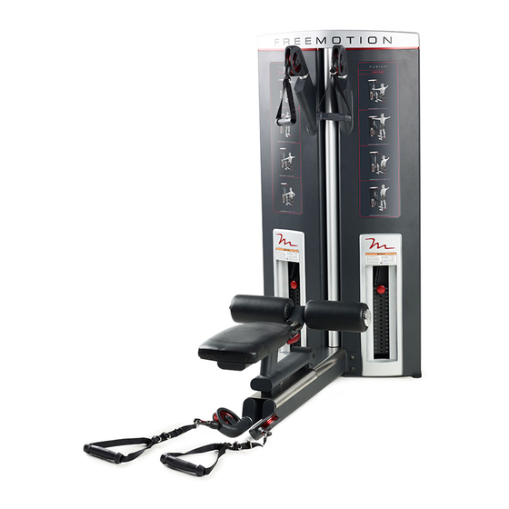
Model No. F505.0
Serial No.
Write the serial number in the space
above for reference.
Serial
Number
Decal
QUESTIONS?
If you have questions, or if parts
are damaged or missing, please
see HOW TO CONTACT
CUSTOMER CARE on the back
cover of this manual.
CAUTION
Read all precautions and instruc-
tions in this manual before using
this equipment. Keep this manual
for future reference.
OWNER’'S MANUAL
www.freemotionfitness.com
Advertisement
Table of Contents

Subscribe to Our Youtube Channel
Related Manuals for Freemotion Delts F505.0


Summary of Contents for Freemotion Delts F505.0
- Page 1 Model No. F505.0 OWNER’’S MANUAL Serial No. Write the serial number in the space above for reference. Serial Number Decal QUESTIONS? If you have questions, or if parts are damaged or missing, please see HOW TO CONTACT CUSTOMER CARE on the back cover of this manual.
-
Page 2: Table Of Contents
LIMITED WARRANTY............. . . Back Cover FREEMOTION is a registered trademark of ICON IP, Inc. -
Page 3: Important Precautions
To reduce the risk of serious injury, read all important precautions and instructions in this manual and all warnings on your strength equipment before using your strength equipment. FreeMotion Fitness assumes no responsibility for personal injury or property damage sustained by or through the use of this product. -
Page 4: Warning Decal Placement
WARNING DECAL PLACEMENT This drawing shows the location(s) of the Decal 2 warning decal(s). If a decal is missing or illegible, see the back cover of this manual and request a free replacement Decal 1 decal. Apply the decal in the location shown. -
Page 5: Before You Begin
BEFORE YOU BEGIN Thank you for selecting the innovative FREEMOTION ® of this manual. To help us assist you, note the product DELTS strength equipment. With unrestricted motion, model number and serial number before contacting us. you can work your body’’s muscle groups together——the The model number and the location of the serial num- same way you do naturally——to train more effectively. -
Page 6: Assembly
ASSEMBLY •• Because of its weight and size, assemble the materials until assembly is completed. strength equipment in the location where it will be used. Make sure that there is enough clearance •• Assembly requires a set of metric hex keys. To around the strength equipment. - Page 7 2. Slide a Pad (18) onto each side of the Pad Frame (4). Attach each Pad with an M6 x 25mm Screw (70) and a Pad Cap (16). 3. Pull the Latch Handle (12), insert the Pad Frame (4) into the Seat Frame (3), and then release the Latch Handle into an adjustment hole in the Pad Frame.
- Page 8 4. Attach the Seat (6) to the Seat Frame (3) with four M8 x 30mm Screws (72) and four M8 Washers (59); start all the Screws, and then tighten them. 5. IMPORTANT: During steps 5––9, set the parts that you remove in separate piles. You will reattach the parts in later steps.
- Page 9 6. Remove the four M10 x 20mm Screws (74), the four M10 Washers (58), and the Tower Brace (8). 7. Remove the four M6 x 16mm Screws (57) and the four M6 Washers (63) from the Cap (38).
- Page 10 8. Remove the two M16 Jam Nuts (76), the two M16 Split Washers (75), the two Weight Guide Spacers (35), and the two Plastic Washers (36) from the upper ends of the two Weight Guides (34) on one side of the Tower (1). Note: After you remove these parts, the Weight Guides (34) will slide downward a few inches into the Tower (1).
- Page 11 10. Hold the Weight Carriage (26), and cut the plas- tic tie (not shown) securing the Weight Carriage to the Tower (1). Then, slide the Weight Carriage upward off the Weight Guides (34). 11. Look at the decals on one of the stacks of Weights (29), and find the decal that has the largest number on it.
- Page 12 12. Note: This step requires the parts that you removed in step 9. Pull the upper ends of the Weight Guides (34) toward you. Tighten the two M16 Jam Nuts (76) as far as possible onto the Weight Guides. Next, slide the two M16 Split Washers (75), the two Weight Guide Spacers (35), and the two Plastic Washers (36) onto the Weight Guides (34).
- Page 13 14. Repeat steps 8––13 on the other side of the strength equipment. Note: This step requires the parts that you removed in step 7. Attach the Cap (38) to the Tower (1) with the four M6 x 16mm Screws (57) and the four M6 Washers (63);...
- Page 14 15. Note: This step requires the parts that you removed in step 6. Attach the Tower Brace (8) to the Tower (1) with the four M10 x 20mm Screws (74) and the four M10 Washers (58); start all the Screws, and then tighten them.
-
Page 15: Adjustment
ADJUSTMENT This section explains how to adjust the strength equipment. Make sure that all parts are properly tightened each time the strength equipment is used. Replace any worn parts immediately. ADJUSTING THE RESISTANCE To change the resistance setting of each weight stack, insert the weight pin into the desired weight. - Page 16 ADJUSTING THE LONG HANDLES Long The long handles can be attached to the cable clips Handle in any of three positions. To attach each long handle, insert the desired ring on the long handle into a cable clip. Ring Cable Clip...
-
Page 17: Maintenance And Troubleshooting
Personnel must also record and report any accident. To maintain the strength equipment’’s warranty, use only FREEMOTION parts for repair or replacement. If there are any questions or concerns, see HOW TO CONTACT CUSTOMER CARE on the back cover of this manual. - Page 18 Cable Traps CABLE ADJUSTMENT To inspect the cable traps, first remove the screws and the cap from the top of the strength equipment. Next, For the strength equipment to function properly, the remove the screws and the access cover from the back cables must be tensioned correctly.
- Page 19 4. Using cable cutters, cut off one inch of the end of 4. Using a punch, drive the four old bushings out of the cable. IMPORTANT: Other tools may flatten the weight carriage. or bend the cable strands so that it may be dif- ficult for you to reinsert the cable into the cable clip.
-
Page 20: Cable Diagram
CABLE DIAGRAM The diagram below shows the proper routes of the cables. The numbers show the correct route of each cable. Use the diagram to make sure that the cables and the cable traps are assembled correctly. If a cable is not cor- rectly routed, the strength equipment will not function properly and damage may occur. -
Page 21: Part List
PART LIST Model No. F505.0 R1213A Key No. Qty. Description Key No. Qty. Description Tower Access Cover Base Pulley Cover A Seat Frame Pulley Cover B Pad Frame Pulley Cover Bushing Frame Sleeve Weight Carriage Bumper Seat Cable End/Clip Arm Pulley Cable Stop Tower Brace Spring... -
Page 22: Exploded Drawing
EXPLODED DRAWING A Model No. F505.0 R1213A... - Page 23 EXPLODED DRAWING B Model No. F505.0 R1213A...
-
Page 24: How To Contact Customer Care
LIMITED WARRANTY WARRANTY PERIODS AND COVERAGE 2. Pick-up and delivery or freight charges involved with a FreeMotion Fitness warrants this product to be free from repair. defects in workmanship and material under normal use and 3. Any problem as a result of improper assembly or delivery.
Need help?
Do you have a question about the Delts F505.0 and is the answer not in the manual?
Questions and answers