Table of Contents
Advertisement
Quick Links
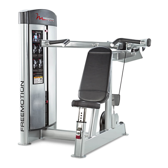
Model No. F807.0
Serial No.
Write the serial number in the
space above for reference.
Serial Number Decal
QUESTIONS?
If you have questions, or if parts
are damaged or missing, please
see HOW TO CONTACT
CUSTOMER CARE on the back
cover of this manual.
CAUTION
Read all precautions and instruc-
tions in this manual before using
this equipment. Keep this manual
for future reference.
OWNERʼS MANUAL
www.freemotionfitness.com
Advertisement
Table of Contents

Related Manuals for Freemotion EPIC SHOULDER F807.0


Summary of Contents for Freemotion EPIC SHOULDER F807.0
- Page 1 Model No. F807.0 Serial No. OWNERʼS MANUAL Write the serial number in the space above for reference. Serial Number Decal QUESTIONS? If you have questions, or if parts are damaged or missing, please see HOW TO CONTACT CUSTOMER CARE on the back cover of this manual.
- Page 2 HOW TO CONTACT CUSTOMER CARE ..........Back Cover FREEMOTION is a registered trademark of ICON IP, Inc.
-
Page 3: Important Precautions
To reduce the risk of serious injury, read all important precautions and instructions in this manual and all warnings on your strength equipment before using your strength equipment. FreeMotion Fitness assumes no responsibility for personal injury or property damage sustained by or through the use of this product. -
Page 4: Warning Decal Placement
WARNING DECAL PLACEMENT This drawing shows the location(s) of the warning decal(s). If a decal is missing or illegible, see the back cover of this manual and request a free replacement decal. Apply the decal in the location shown. Note: The decal(s) may not be shown at actual size. -
Page 5: Before You Begin
BEFORE YOU BEGIN Thank you for selecting the FREEMOTION EPIC™ of this manual. To help us assist you, note the product ® SHOULDER strength equipment. With unrestricted model number and serial number before contacting us. motion, you can work your bodyʼs muscle groups the... -
Page 6: Part Identification Chart
PART IDENTIFICATION CHART Refer to the drawings below to identify small parts used for assembly. The number in parentheses by each draw- ing is the key number of the part, from the PART LIST near the end of this manual. The number following the parentheses is the quantity needed for assembly. -
Page 7: Assembly
ASSEMBLY • Assembly requires two persons. • The following tools (not included) are required for assembly: • Because of its weight and size, assemble the one adjustable wrench strength equipment in the location where it will be used. Make sure that there is enough clearance one Phillips screwdriver around the strength equipment. - Page 8 2. Orient the Tower Frame (1) as shown. Have a second person hold the Tower Frame to pre- vent it from falling until you complete step Remove the two M10 x 30mm Socket Patch Screws (30), the two M10 Washers (31), and the Small Pulley Bracket (6) from the back of the Tower Frame (1).
- Page 9 4. Route the Long Cable (40) upward through the Small Pulley Bracket (6). Attach the Large Pulley (24) inside the Small Pulley Bracket (6) with the M10 x 50mm Socket Bolt (29), the two M10 Washers (31), and the M10 Locknut (32) that you removed in step 2. Then, attach the Small Pulley Bracket (6) to the Tower Frame (1) with the two M10 x 30mm Socket Patch Screws (30) and the two M10...
-
Page 10: Forward Or Backward, And Slide The Two
6. Loosen the two M8 x 35mm Set Screws (19) a few complete turns; it is not necessary to 19 18 remove the Set Screws. Look under the top of the Tower Frame (1) and remove the two 25mm Snap Rings (39) from the two Weight Guide Bushings (18). -
Page 11: The Two Weight Guide Bushings (18
8. Orient the Top Weight (9) and the Drop-down Weight (10) as shown. Slide the Top Weight (9), the two Upper Weight Bumpers (16), the Drop-down Weight (10), and the two 25mm Snap Rings (39) onto the Weight Guides (7). Next, slide the two Weight Guide Bushings (18) onto the upper ends of the Weight Guides (7). - Page 12 10. Tighten the end of the Long Cable (40) into the Weight Selector (11) until the Top Weight (9) is lifted off the Weights (8, 44). Then, loosen the end of the Long Cable until the Top Weight just rests on the Weights. Then, tighten the jam nut on the end of the Long Cable (40) against the Weight Selector (11).
- Page 13 12. Orient the Right Arm (49) as shown. Insert the Right Arm (49) and two Plastic Washers (56) inside the right top bracket on the Base (72). Then, slide the Arm Axle (53) through the Plastic Washers (56) and the Right Arm (49). Attach a 25mm Snap Ring (39) to each end of the Arm Axle (53).
- Page 14 14. See the CABLE DIAGRAM on page 22 and identify the Medium Cable (59). Attach a Ball Joint (68) on the end of the Medium Cable (59) to the Right Arm (49) with an M10 x 35mm Socket Patch Screw (76) and an M10 Washer (31).
- Page 15 16. Route the Short Cable (60) under the pulley on the Cam (50), upward through the Base (72), and over the pulley on the Cam. Then, press the end of the Short Cable (60) as far as possible into the socket on the Cam (50). 17.
- Page 16 18. Remove the indicated M10 x 18mm Stop Screw (70) from the Base (72). Press the indicated Adjustment Latch (66) on the Base (72), insert the Seat Frame (45) into the Base, and then release the Adjustment Latch into one of the adjustment holes in the Seat Frame.
- Page 17 20. Look at the four Shrouds (36), and identify the two Shrouds that have strips of Inner Trim (37) and the two Shrouds that do not. Slide the Shroud Panel (46) downward onto the two Shrouds (36) that do not have strips of Inner Trim (37).
- Page 18 22. Slide the two remaining Shrouds (36) downward into the two strips of Outer Trim (5) on the front of the Tower Frame (1). 23. Orient the Tower Cap (2) as shown. Slide the Tower Cap (2) downward onto the Tower Frame (1).
-
Page 19: Adjustment
ADJUSTMENT This section explains how to adjust the strength equipment. Make sure all that parts are properly tightened each time the strength equipment is used. Replace any worn parts immediately. ADJUSTING THE RESISTANCE To change the amount of resistance, insert the weight pin into the desired weight. -
Page 20: Maintenance And Troubleshooting
Personnel must also record and report any accident. To maintain the strength equipmentʼs warranty, use only FREEMOTION parts for repair or replacement. If there are any questions or concerns, see HOW TO CONTACT CUSTOMER CARE on the back cover of this manual. - Page 21 Cable Adjustment MONTHLY MAINTENANCE To determine whether each cable is properly adjusted, Grips slowly raise and lower the top weight by performing one repetition. Check the grips and replace them if needed. Weight Guide Lubrication If the cable is loose, the top weight will not be lifted immediately when you begin the repetition.
-
Page 22: Cable Diagram
CABLE DIAGRAM The diagram below shows the correct route of each cable. The numbers in each drawing show the correct route of that cable. Use the diagram to make sure that each cable is correctly routed. If a cable is not correctly routed, the strength equipment will not function properly and damage may occur. - Page 23 NOTES...
- Page 24 NOTES...
-
Page 25: Part List
PART LIST Model No. F807.0 R1110A Key No. Qty. Description Key No. Qty. Description Tower Frame V-pulley Tower Cap Anchor Strap Rear Shroud Base 10-pound Weight Front Shroud Base Seat Frame Outer Trim Shroud Panel Small Pulley Bracket M10 x 110mm Socket Patch Screw Weight Guide Left Arm 20-pound Weight... -
Page 26: Exploded Drawing
EXPLODED DRAWING A Model No. F807.0 R1110A 13 12... - Page 27 EXPLODED DRAWING B Model No. F807.0 R1110A...
- Page 28 PART LIST and the EXPLODED DRAWING near the end of this manual). In the United States and Canada Call: 1-800-201-2109, Mon.–Fri. 8 a.m.–5 p.m. MT Write: FreeMotion Fitness 1500 South 1000 West Logan, UT 84321-9813 United States Outside the United States and Canada Call: 001-435-786-3521 Email: intlcustomercare@freemotionfitness.com...
Need help?
Do you have a question about the EPIC SHOULDER F807.0 and is the answer not in the manual?
Questions and answers