Table of Contents
Advertisement
Model No. F218.0
Serial No.
Write the serial number in the space
OWNER'S MANUAL
above for reference.
Serial Number
Decal
QUESTIONS?
If you have questions, or if
parts are damaged or missing,
please see HOW TO CONTACT
CUSTOMER CARE on the back
cover of this manual.
CAUTION
Read all precautions and
instructions in this manual before
using this equipment. Keep this
manual for future reference.
freemotionfitness.com
Advertisement
Table of Contents

Subscribe to Our Youtube Channel
Related Manuals for Freemotion F218.0


Summary of Contents for Freemotion F218.0
- Page 1 Model No. F218.0 Serial No. Write the serial number in the space OWNER’S MANUAL above for reference. Serial Number Decal QUESTIONS? If you have questions, or if parts are damaged or missing, please see HOW TO CONTACT CUSTOMER CARE on the back cover of this manual.
-
Page 2: Table Of Contents
Note: The decal(s) may not be shown at actual size. FREEMOTION is a registered trademark of ICON Health & Fitness, Inc. FORMULA 409 is a registered trademark of The Clorox Company. SIMPLE GREEN is a registered trademark of Sunshine Makers, Inc. -
Page 3: Important Precautions
To reduce the risk of serious injury, read all important precautions and instructions in this manual and all warnings on your strength equipment before using your strength equipment. FreeMotion Fitness assumes no responsibility for personal injury or property damage sustained by or through the use of this product. -
Page 4: Before You Begin
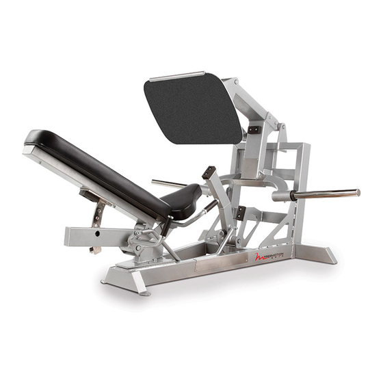
BEFORE YOU BEGIN Thank you for selecting the FREEMOTION PLATE questions after reading this manual, please see the ® LOADED LEG PRESS strength equipment. The PLATE back cover of this manual. To help us assist you, note LOADED LEG PRESS is designed to help you develop the product model number and serial number before the major muscle groups of your upper body. -
Page 5: Part Identification Chart
PART IDENTIFICATION CHART This chart is provided to help you identify the small parts used in assembly. The number in parentheses below each part is the key number of the part from the PART LIST near the end of this manual. The number following the parentheses is the quantity needed for assembly. -
Page 6: Assembly
ASSEMBLY • Assembly requires two persons. • Assembly requires the following tools (not included): • Because of its weight and size, the strength an adjustable wrench equipment should be assembled in the location where it will be used. Make sure that there is a metric hex key enough clearance to walk around the strength equipment as you assemble it. - Page 7 2. Attach the Seat Frame (2) to the Base (1) with two M12 x 35mm Screws (40), two M12 x 40mm Bolts (58), and two M12 Locknuts (27). 3. Identify the Weight Frame (38) and orient it as shown. Attach the Weight Frame (38) to the Foot Plate Frame (4) with four M12 x 90mm Screws (17), the Frame Plate (62), two M12 x 175mm Bolts (18), and two M12 Locknuts (27).
- Page 8 4. Identify the Right Adjustment Arm (10), which is attached to the Seat Frame (2). Attach the Support Arm (7) to the Right Adjustment Arm (10) with an M10 x 30mm Bolt (52), an M10 Nylon Washer (63), and an M10 Locknut (48).
- Page 9 6. Orient the Backrest (14) as shown. Attach the Backrest (14) to the Backrest Frame (3) with two M8 x 80mm Screws (59). 7. Attach the Seat (15) to the Seat Frame (2) with four M8 x 25mm Screws (46). 8.
-
Page 10: Adjustment
ADJUSTMENT This section explains how to adjust the strength equipment. Make sure that all parts are properly tightened each time the strength equipment is used. Replace any worn parts immediately. ADDING WEIGHTS TO THE WEIGHT ARM To add resistance to your workout, slide the same amount of weight (not included) onto both Weight Bars (13). -
Page 11: Maintenance And Troubleshooting
Personnel must also record and report any accident. To maintain the strength equipment’s warranty, use only FREEMOTION parts for repair or replacement. If there are any questions or concerns, see HOW TO CONTACT CUSTOMER CARE on the back cover of this manual. - Page 12 NOTES...
-
Page 13: Part List
PART LIST Model No. F218.0 R0417A Key No. Qty. Description Key No. Qty. Description Base Small Bearing Seat Frame Small Nylon Washer Backrest Frame Small Retainer Ring Foot Plate Frame Weight Bumper Foot Plate Weight Frame Foot Plate Arm M10 x 75mm Screw... -
Page 14: Exploded Drawing
EXPLODED DRAWING A Model No. F218.0 R0417A 31 32 34 35 21 50... - Page 15 EXPLODED DRAWING B Model No. F218.0 R0417A...
-
Page 16: How To Contact Customer Care
LIMITED WARRANTY WARRANTY PERIODS AND COVERAGE 2. Pick-up and delivery or freight charges involved with a FreeMotion Fitness warrants this product to be free from repair. defects in workmanship and material under normal use and 3. Any problem as a result of improper assembly or delivery.
Need help?
Do you have a question about the F218.0 and is the answer not in the manual?
Questions and answers