
Related Manuals for Ruckus Wireless ICX 7650


Summary of Contents for Ruckus Wireless ICX 7650
- Page 1 HARDWARE INSTALLATION GUIDE Ruckus ICX 7650 Switch Hardware Installation Guide Part Number: 53-1005301-01 Publication Date: 21 December 2017...
- Page 2 Copyright © 2017, Brocade Communications Systems, Inc. All Rights Reserved. Brocade, Brocade Assurance, the B-wing symbol, ClearLink, DCX, Fabric OS, HyperEdge, ICX, MLX, MyBrocade, OpenScript, VCS, VDX, Vplane, and Vyatta are registered trademarks, and Fabric Vision is a trademark of Brocade Communications Systems, Inc., in the United States and/or in other countries.
-
Page 3: Table Of Contents
............. . . 3 Port-side views of the Ruckus ICX 7650 switches . - Page 4 ..............57 Grounding the Ruckus ICX 7650 switch Ruckus ICX 7650 Switch Hardware Installation Guide Part Number: 53-1005301-01...
- Page 5 ........66 Resolving Module 2 mismatches in a standalone Ruckus ICX 7650 switch .
- Page 6 DRAFT: BROCADE CONFIDENTIAL Ruckus ICX 7650 Switch Hardware Installation Guide Part Number: 53-1005301-01...
-
Page 7: Preface
Command syntax conventions Bold and italic text identify command syntax components. Delimiters and operators define groupings of parameters and their logical relationships. Ruckus ICX 7650 Switch Hardware Installation Guide Part Number: 53-1005301-01... -
Page 8: Document Feedback
Access to Release Notes requires an active support contract and Ruckus Support Portal user account. Other technical documentation content is available without logging into the Ruckus Support Portal. White papers, data sheets, and other product documentation are available at https://www.ruckuswireless.com. viii Ruckus ICX 7650 Switch Hardware Installation Guide Part Number: 53-1005301-01... -
Page 9: Online Training Resources
Ruckus products, including: • Technical Documentation—https://support.ruckuswireless.com/documents • Community Forums—https://forums.ruckuswireless.com/ruckuswireless/categories • Knowledge Base Articles—https://support.ruckuswireless.com/answers • Software Downloads and Release Notes—https://support.ruckuswireless.com/software • Security Bulletins—https://support.ruckuswireless.com/security Ruckus ICX 7650 Switch Hardware Installation Guide Part Number: 53-1005301-01... - Page 10 Using these resources will help you to resolve some issues, and will provide TAC with additional data from your troubleshooting analysis if you still require assistance through a support case or RMA. If you still require help, open and manage your case at https:// support.ruckuswireless.com/case_management Ruckus ICX 7650 Switch Hardware Installation Guide Part Number: 53-1005301-01...
-
Page 11: About This Document
Supported hardware and software ..............1 Supported hardware and software The following tables list the power supplies, fan assemblies, and rack mount kits supported on the Ruckus ICX 7650 switch running Ruckus FastIron 08.0.70. - Page 12 DRAFT: BROCADE CONFIDENTIAL About This Document Supported hardware and software Ruckus ICX 7650 Switch Hardware Installation Guide Part Number: 53-1005301-01...
-
Page 13: Device Overview
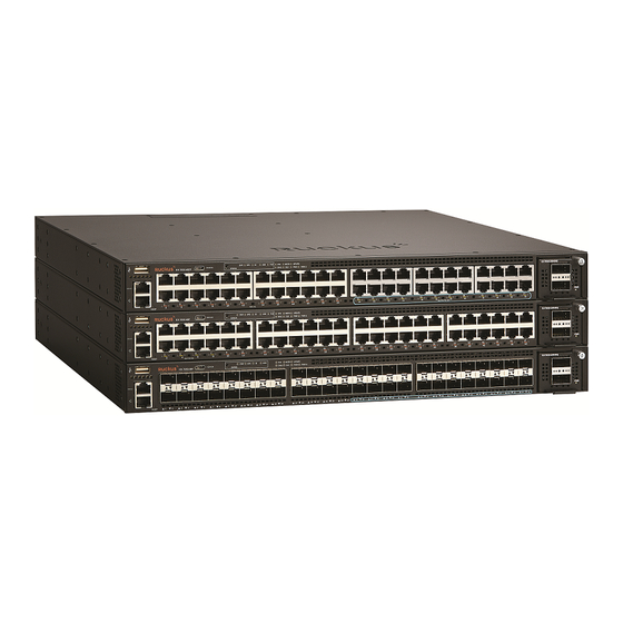
ICX 7650-48P copper ports support PoE, PoE+, High PoE, and PoH • ICX 7650-48F SFP ports support 100 MbE or 1 GbE transceivers and SFP+ ports support 1 GbE or 10 GbE transceivers • 10 GbE SFP+ expansion module with four 1/10 GbE SFP+ ports •... - Page 14 25-48 supporting High PoE/PoH 11 Module 2 — expansion module ports Figure 2 shows the front view of the Ruckus ICX 7650-48P switch. NOTE High PoE/PoH is limited to ports 1-8. PoE/PoE+ power is available to ports 9-48. FIGURE 2...
-
Page 15: Nonport-Side View Of The Ruckus Icx 7650 Switch
DRAFT: BROCADE CONFIDENTIAL Device Overview Nonport-side view of the Ruckus ICX 7650 switch Figure 3 shows the front view of the Ruckus ICX 7650-48F switch. FIGURE 3 Front view of the Ruckus ICX 7650-48F USB port (for flash drive) Mini-USB console port... -
Page 16: Device Management Options
Ethernet or serial connection Ruckus FastIron Command Reference REST or NETCONF/YANG APIs. Ethernet connection Ruckus FastIron Management Configuration Guide Standard SNMP applications Ethernet or serial connection Ruckus FastIron Management Configuration Guide Ruckus ICX 7650 Switch Hardware Installation Guide Part Number: 53-1005301-01... -
Page 17: Preparing For Installation Safety Precautions
Ensure that the airflow direction of the power supply unit matches that of the installed fan tray. The power supplies and fan trays are clearly labeled with either a green arrow with an "E", or an orange arrow with an "I." Ruckus ICX 7650 Switch Hardware Installation Guide Part Number: 53-1005301-01... -
Page 18: Esd Precautions
The mark is your assurance that the power cord can be used safely with the device. Ruckus ICX 7650 Switch Hardware Installation Guide Part Number: 53-1005301-01... -
Page 19: Lifting Precautions
To prevent damage to the chassis and components, never attempt to lift the chassis using the fan or power supply handles. These handles were not designed to support the weight of the chassis. Laser precautions DANGER All fiber-optic interfaces use Class 1 lasers. Ruckus ICX 7650 Switch Hardware Installation Guide Part Number: 53-1005301-01... -
Page 20: Facility Requirements
• Because the Ruckus ICX 7650 switch can be ordered with fans that move air either front to back or back to front, be sure to orient your switch with the airflow pattern of any other devices in the rack. All equipment in the rack should force air in the same direction to avoid intake of exhaust air. -
Page 21: Rack Considerations
Ensure that the physical environment that will host the device has the proper “Facility requirements” on page 10 cabling and ventilation. If customizing a Ruckus ICX 7650 switch baseline chassis: “Inserting a new AC power supply” on page 56 Install at least one power supply unit. - Page 22 Test IP connectivity to other devices by pinging them and tracing routes. Ruckus FastIron Command Reference Continue configuring the device using the CLI. Ruckus FastIron Command Reference Secure access to the device. Ruckus FastIron Management Configuration Guide Ruckus ICX 7650 Switch Hardware Installation Guide Part Number: 53-1005301-01...
-
Page 23: Mounting The Device
Connecting devices in a stack ............... . . 28 Mounting options You can install the Ruckus ICX 7650 in the following ways: •... -
Page 24: Installing The Device On A Desktop
Do not install the device in an environment where the operating ambient temperature might exceed 50°C (122°F). Installing the device on a desktop Complete the following steps to install the Ruckus ICX 7650 on a desktop or other flat surface. FIGURE 5 Attaching the adhesive feet Attach the four adhesive feet to the bottom of the device. -
Page 25: Two-Post Rack Mount Installation
Two-post rack, side view NOTE Use the following procedure when installing the Ruckus ICX 7650 in a two-post rack. For four-post racks, follow the procedures “Installing the 1U, 1.5U, and 2U Universal Kit for Four-Post Racks (XBR-R000295)” on page 17. - Page 26 FIGURE 7 Attaching the mounting brackets for a Ruckus ICX 7650 Position the device in the rack, providing temporary support under the switch until the rail kit is secured to the rack. Attach the front right bracket to the rail rack using two 10-32 x 5/8 in. screws and the appropriate round-hole or square-hole retainer nuts.
-
Page 27: Installing The 1U, 1.5U, And 2U Universal Kit For Four-Post Racks (Xbr-R000295)
• #2 Phillips torque screwdriver • 1/4-inch slotted-blade torque screwdriver Parts list The following parts are provided with the 1U, 1.5U, and 2U Universal Kit for Four-Post Racks Installation (XBR-R000295). Ruckus ICX 7650 Switch Hardware Installation Guide Part Number: 53-1005301-01... -
Page 28: Flush-Front Mounting The Device In The Rack
“Installing the device in the rack” on page 20 “Attaching the rear brackets to the extensions” on page 21 “Attaching the rear brackets to the rack posts” on page 22 Ruckus ICX 7650 Switch Hardware Installation Guide Part Number: 53-1005301-01... - Page 29 Repeat Step 1 and Step 2 to attach the left extension bracket to the left side of the device. Tighten all the 8-32 x 5/16-in. screws to a torque of 15 in-lb (17 cm-kg). Ruckus ICX 7650 Switch Hardware Installation Guide Part Number: 53-1005301-01...
- Page 30 Attach the left front bracket to the left front rack post using two 10-32 x 5/8-in. panhead screws and two retainer nuts. Use the upper and lower holes in the bracket. Tighten all the 10-32 x 5/8-in. screws to a torque of 25 in-lb (29 cm-kg). Ruckus ICX 7650 Switch Hardware Installation Guide Part Number: 53-1005301-01...
- Page 31 Repeat step 2 and step 3 to attach the left rear bracket to the left extension. Adjust the brackets to the rack depth and tighten all the 6-32 x 1/4-in. screws to a torque of 9 in-lb (10 cm-kg). Ruckus ICX 7650 Switch Hardware Installation Guide Part Number: 53-1005301-01...
- Page 32 Attach the left rear bracket to the left rear rack post using two 10-32 x 5/8-in. panhead screws and two retainer nuts. Use the upper and lower holes in the bracket. Tighten all the 10-32 x 5/8-in. screws to a torque of 25 in-lb (29 cm-kg). Ruckus ICX 7650 Switch Hardware Installation Guide Part Number: 53-1005301-01...
-
Page 33: Flush-Rear (Recessed) Mounting The Device In The Rack
25 “Attaching the rear brackets to the extensions at the front of the device” on page 26 “Attaching the rear brackets to the front rack posts” on page 27 Ruckus ICX 7650 Switch Hardware Installation Guide Part Number: 53-1005301-01... - Page 34 Select the proper length extension bracket for your rack depth. Position the right extension along the side of the device as shown in Figure Attach the bracket using four 8-32 x 5/16-in. flathead screws. Ruckus ICX 7650 Switch Hardware Installation Guide Part Number: 53-1005301-01...
- Page 35 Attach the left front bracket to the left rear rack post using two 10-32 x 5/8-in. panhead screws and two retainer nuts. Use the upper and lower holes in the bracket. Tighten all the 10-32 x 5/8-in. screws to a torque of 25 in-lb (29 cm-kg). Ruckus ICX 7650 Switch Hardware Installation Guide Part Number: 53-1005301-01...
- Page 36 Repeat Step 2 and Step 3 to attach the left rear bracket to the left extension. Adjust the brackets to the rack depth and tighten all the 6-32 x 1/4-in. screws to a torque of 9 in-lb (10 cm-kg). Ruckus ICX 7650 Switch Hardware Installation Guide Part Number: 53-1005301-01...
- Page 37 Rear bracket, medium or long Screws, 6-32 x 1/4-in., panhead Phillips Attaching the rear brackets to the front rack posts Complete the following steps to attach the rear brackets to the front rack posts. Ruckus ICX 7650 Switch Hardware Installation Guide Part Number: 53-1005301-01...
-
Page 38: Connecting Devices In A Stack
Connecting devices in a stack The Ruckus ICX 7650 can operate as a standalone device or as a member of a stack. A stack is a group of devices—Ruckus stackable units and their connected stacking links—that are connected so that the stack is managed as a single entity. -
Page 39: Stacking Configuration Requirements
Use QSFP+/QSFP28 direct attached copper stacking cables or QSFP+/QSFP28 optics with fiber cables to connect the Ruckus ICX 7650 devices in a stack. The copper cable lengths for 40 GbE ports are 0.5 meter, 1 meter, 3 meters, or 5 meters. - Page 40 For example, in a three-unit stack using a ring topology, unit 1 connects to unit 2, unit 2 connects to unit 3, and unit 3 connects to unit 1. Figure 25 shows a supported ring stacking topology using the 100 GbE stacking ports. Ruckus ICX 7650 Switch Hardware Installation Guide Part Number: 53-1005301-01...
- Page 41 40 GbE ring stacking topology using 40 GbE and 40/100 GbE stacking ports. FIGURE 26 40 GbE ring stacking topology NOTE For more information about stacking, refer to the Ruckus FastIron Stacking Configuration Guide. Ruckus ICX 7650 Switch Hardware Installation Guide Part Number: 53-1005301-01...
- Page 42 DRAFT: BROCADE CONFIDENTIAL Mounting the Device Connecting devices in a stack Ruckus ICX 7650 Switch Hardware Installation Guide Part Number: 53-1005301-01...
-
Page 43: Initial Setup And Verification
Connect the serial cable to the console port on the device and to an RS-232 serial port on the workstation using the included RJ-45-to-RS-232 adapter. Connect a PC or terminal to the console management port on the front of the Ruckus ICX 7650 using the mini-USB serial console port cable. -
Page 44: Establishing An Ethernet Connection
The Gigabit Ethernet management port (RJ-45) on the Ruckus ICX 7650 front panel provides an out-of-band network connection to the device. After you assign an IP address, you can access the Ruckus ICX 7650 from anywhere in the attached network using Telnet, a web browser, or other network management tools, such as Ruckus Network Advisor. -
Page 45: Installing Transceivers And Cables
To clean the fiber cable connectors, Ruckus recommends using a fiber-optic reel-type cleaner. When not using a fiber-optic transceiver connector, make sure to keep the protective covering in place. Ruckus ICX 7650 Switch Hardware Installation Guide Part Number: 53-1005301-01... -
Page 46: Managing Cables
Before installing a fiber-optic transceiver, have an ESD wrist strap available with a plug for connection to the ESD connector on the device. DANGER For safety reasons, the ESD wrist strap should contain a series 1 megohm resistor. DANGER Laser radiation. Do not view directly with optical instruments. Class 1M laser products. Ruckus ICX 7650 Switch Hardware Installation Guide Part Number: 53-1005301-01... -
Page 47: Replacing A Fiber-Optic Transceiver
FIGURE 27 Installing an SFP+ transceiver in a port slot SFP+ transceiver Replacing a fiber-optic transceiver You can remove a fiber-optic transceiver from a slot and replace it with a new one while the Ruckus ICX 7650 switch is powered on and running. Removing a fiber-optic transceiver While removing a fiber-optic transceiver, be sure to wear an ESD wrist strap that is connected to ground. -
Page 48: Connecting Network Devices
MDI or MDIX, designate the port as an MDI port, or designate the port as an MDIX port. For more information about automatic MDI or MDIX detection and configuration details, refer to the Ruckus FastIron Management Configuration Guide. Ruckus ICX 7650 Switch Hardware Installation Guide Part Number: 53-1005301-01... -
Page 49: Connecting A Network Device To A Fiber Port
41. NOTE To verify that a Ruckus ICX 7650 switch can reach another device through the network, use the ping command at any level of the CLI. For more information, refer to the Ruckus FastIron Management Configuration Guide. - Page 50 DRAFT: BROCADE CONFIDENTIAL Installing Transceivers and Cables Connecting network devices Ruckus ICX 7650 Switch Hardware Installation Guide Part Number: 53-1005301-01...
-
Page 51: Monitoring The Device
LEDs do not indicate a healthy state after all boot processes and diagnostic tests are complete. Ruckus ICX 7650 port-side LEDs The Ruckus ICX 7650-48ZP has the following LEDs on the front panel: • Two management port status LEDs (green) for speed and link/activity •... - Page 52 Figure 28 shows the LEDs on the Ruckus ICX 7650-48ZP front panel. The up-arrow port status LEDs for the 1 GbE and 2.5/5/10 GbE ports correspond to the upper, odd-numbered ports; the down-arrow port status LEDs correspond to the lower, even-numbered ports.
- Page 53 1x40 GbE mode of operation. Figure 29 shows the LEDs on the Ruckus ICX 7650-48P front panel. The up-arrow port status LEDs for the 1 GbE ports correspond to the upper, odd-numbered ports; the down-arrow port status LEDs correspond to the lower, even-numbered ports.
- Page 54 1x40 GbE mode of operation. Figure 30 shows the LEDs on the Ruckus ICX 7650-48F front panel. The up-arrow port status LEDs for the 1/10 GbE ports correspond to the upper, odd-numbered ports; the down-arrow port status LEDs correspond to the lower, even-numbered ports.
-
Page 55: Ruckus Icx 7650 Nonport-Side Leds
12 Management port speed LED Ruckus ICX 7650 nonport-side LEDs The Ruckus ICX 7650 has the following LEDs on the rear panel: • Four single-color status LEDs (green) for each of the two 40 GbE rear-module stacking ports that indicate the status of the ports in 1x40 GbE or 4x10 GbE mode. -
Page 56: Status Mode Button And Leds
A USB copy operation has failed, there has been an application error, Contact support. or the USB is present but there is a mount failure/access failure. LED patterns The following tables describe the Ruckus ICX 7650 LED patterns. TABLE 4 Management port left (10/100/1000 Mbps) status LED LED state... - Page 57 Blinking green The switch is trying to connect to a cloud management platform. No action required. Steady green The switch is successfully connected to a cloud management No action required. platform. Ruckus ICX 7650 Switch Hardware Installation Guide Part Number: 53-1005301-01...
- Page 58 Port is operating at its 4th highest speed. No action required. • Multi GbE ports: 1 Gbps Alternating amber/green Port is operating at its 5th highest speed. No action required. • Multi GbE ports: 100 Mbps Ruckus ICX 7650 Switch Hardware Installation Guide Part Number: 53-1005301-01...
- Page 59 Steady amber Port lane link is up in 10 GbE mode. No action required. Blinking amber There is 10 GbE traffic and packets are being transmitted or received. No action required. Ruckus ICX 7650 Switch Hardware Installation Guide Part Number: 53-1005301-01...
-
Page 60: Diagnostic Tests And Monitoring
The following commands can be especially helpful in monitoring the health status of various device components. For details about these commands, refer to the Ruckus FastIron Management Configuration Guide. • show chassis • show system • show environment fan • show environment power • show environment sensor Ruckus ICX 7650 Switch Hardware Installation Guide Part Number: 53-1005301-01... - Page 61 DRAFT: BROCADE CONFIDENTIAL Monitoring the Device Diagnostic tests and monitoring • show environment temp Ruckus ICX 7650 Switch Hardware Installation Guide Part Number: 53-1005301-01...
- Page 62 DRAFT: BROCADE CONFIDENTIAL Monitoring the Device Diagnostic tests and monitoring Ruckus ICX 7650 Switch Hardware Installation Guide Part Number: 53-1005301-01...
-
Page 63: Power Supplies
Ruckus recommends that the Ruckus ICX 7650 switch operates with two power supplies and two fan trays installed. If a power supply or fan tray fails, it must be replaced as soon as possible. The power supplies in the Ruckus ICX 7650 switch chassis can be removed and replaced without special tools. The device can continue operating during the replacement. -
Page 64: Power Supply Usage
For example, a Ruckus ICX 7650-48P has two power supplies installed. If you increase the maximum number of PoE ports that can be supported, and if the primary power supply fails, the redundant power supply cannot guarantee the device is protected by backup power. -
Page 65: Identifying The Airflow Direction
Power supplies can be swapped in or out while the device is running. The remaining power supply provides enough power for the device. • The airflow direction of the power supply must match that of the installed fan assemblies. All must be either exhaust or intake. Ruckus ICX 7650 Switch Hardware Installation Guide Part Number: 53-1005301-01... -
Page 66: Inserting A New Ac Power Supply
When the Ruckus ICX 7650 switch is powered on, the LEDs on the power supply rear panel should light up green to confirm that the power supply is correctly installed and supplying power. -
Page 67: Grounding The Ruckus Icx 7650 Switch
Grounding the Ruckus ICX 7650 switch The rear panel of the Ruckus ICX 7650 switch includes a dual-screw grounding terminal for chassis grounding. The surface area around this terminal is not painted to provide a good electrical connection. Before connecting power to the device, connect the grounding lug to ground the chassis if required by your local building code or regulatory compliance.. - Page 68 DRAFT: BROCADE CONFIDENTIAL Power Supplies Grounding the Ruckus ICX 7650 switch Ruckus ICX 7650 Switch Hardware Installation Guide Part Number: 53-1005301-01...
-
Page 69: Fan Assembly Overview
The fan assemblies in the Ruckus ICX 7650 switch chassis can be removed and replaced without special tools. The device can continue operating during the replacement. -
Page 70: Precautions Specific To Fan Assemblies
Exhaust power supply and fan assembly with a green "E" label: Pulls air from the port side of the switch and exhausts it out the nonport-side. • Nonport-side air exhaust • Port-side air intake • Front-to-back (port-side to nonport-side) airflow • Part numbers ending with -F Ruckus ICX 7650 Switch Hardware Installation Guide Part Number: 53-1005301-01... -
Page 71: Time And Items Required
“E”, or an orange arrow with an "I." Inserting a new fan assembly Use the following steps to install a fan assembly in the Ruckus ICX 7650 switch. FIGURE 36 Installing a fan assembly... - Page 72 If you do not install a module or a power supply in a slot, you must keep the slot filler panel in place. If you run the chassis with an uncovered slot, the system will overheat. Ruckus ICX 7650 Switch Hardware Installation Guide Part Number: 53-1005301-01...
-
Page 73: Expansion Modules
Expansion module overview The Ruckus ICX 7650 includes one port-side slot for media expansion modules, including a 4-port SFP+ 10 GbE module, a 2-port QSFP+ 40 GbE module, and a 1-port QSFP28 100 GbE module. If not installed, the empty expansion module slot must be covered using a filler panel. -
Page 74: Precautions Specific To Expansion Modules
Time and items required Replacing an expansion module in the Ruckus ICX 7650 should take less than two minutes to complete. You need the following items to replace an expansion module in the Ruckus ICX 7650: •... -
Page 75: Installing Or Replacing An Expansion Module
Expansion Modules Installing or replacing an expansion module Installing or replacing an expansion module Complete the following steps to install or replace an expansion module in the Ruckus ICX 7650. Power off the switch. CAUTION The expansion modules are not hot-swappable. -
Page 76: Resolving Module 2 Mismatches
When these configuration mismatches occur, action must be taken to resolve the mismatch. The procedures to resolve a Module 2 mismatch in a standalone Ruckus ICX 7650 switch and a mismatch in a Ruckus ICX 7650 stack are different. -
Page 77: Resolving Module 2 Mismatches In An Ruckus Icx 7650 Stack
Resolving Module 2 mismatches in an Ruckus ICX 7650 stack When an ICX 7650 stack unit rejoins a stack with a different module type installed as Module 2, a configuration mismatch occurs, and the active controller places the stack unit in non-operational mode. - Page 78 -3/1| 1 |3/2--3/2| 4 |3/1--3/1| 3 |3/2--3/2| 2 |3/1- +---+ +---+ +---+ +---+ |--------------------------------------------------| Will assign standby in 49 sec due to all ready Standby u2 - protocols ready, can failover Ruckus ICX 7650 Switch Hardware Installation Guide Part Number: 53-1005301-01...
-
Page 79: Ruckus Icx 7650 Specifications
Non-blocking shared-memory switch System processors BCM58712D with quad-core ARM Cortex-A57 processor running at 1.6 GHz Ethernet These are standard modules for shipping bundles. For Ruckus ICX 7650 non-bundled switches, expansion modules need to be ordered separately. System component Description Maximum ports supported... -
Page 80: Leds
40.64 cm 7.50 kg 1.72 inches 17.32 inches 16 inches 16.5 lb ICX 7650-48F 4.37 cm 44.00 cm 40.64 cm 7.10 kg 1.72 inches 17.32 inches 16 inches 15.62 lb Ruckus ICX 7650 Switch Hardware Installation Guide Part Number: 53-1005301-01... -
Page 81: Environmental Requirements
1 x 1000 W AC 1 PSU, 443 BTU/hr 488 BTU/hr no PoE load. 128.2 W 141.1 W 1 x 1000 W AC 2 PSUs, 438 BTU/hr 482 BTU/hr no PoE load Ruckus ICX 7650 Switch Hardware Installation Guide Part Number: 53-1005301-01... -
Page 82: Power Consumption (Maximum Configuration)
Maximum = 16.68 W ICX-FAN12-I Power-supply intake airflow fan (two fans required if two Typical = 4.68 W power supplies are used) Maximum = 16.68 W Ruckus ICX 7650 Switch Hardware Installation Guide Part Number: 53-1005301-01... -
Page 83: Data Port Specifications (Ethernet)
Not used UART0_RX Debug port (data received by ICX) UART0_TX Console port (data transmitted by ICX) Reserved Not used Ground Serial port specifications (pinout RJ-45) Signal Description Not supported Not supported Ruckus ICX 7650 Switch Hardware Installation Guide Part Number: 53-1005301-01... -
Page 84: Serial Port Specifications (Protocol)
CNS 13438 (BSMI) (Taiwan) (Class A) • KN 32 (South Korea) (Class A) • KN 35 (South Korea) (Class A) • TCVN 7189 / TCVN 7317 (Vietnam) (Class A) • EN 61000-3-2 Ruckus ICX 7650 Switch Hardware Installation Guide Part Number: 53-1005301-01... -
Page 85: Regulatory Compliance (Safety)
30/2011/TT-BCT – Vietnam circular • SJ/T 11363-2006 Requirements for Concentration Limits for Certain Hazardous Substances in EIPs (China) • SJ/T 11364-2006 Marking for the Control of Pollution Caused by EIPs (China) Ruckus ICX 7650 Switch Hardware Installation Guide Part Number: 53-1005301-01... - Page 86 DRAFT: BROCADE CONFIDENTIAL Ruckus ICX 7650 Specifications Regulatory compliance (environmental) Ruckus ICX 7650 Switch Hardware Installation Guide Part Number: 53-1005301-01...
-
Page 87: Regulatory Statements
Maschinenlärminformations-Verordnung - 3. GPSGV, der höchste Schalldruckpegel beträgt 52 dB(A) gemäss EN ISO 7779. English translation of above statement Machine noise information regulation - 3. GPSGV, the highest sound pressure level value is 52 dB(A) in accordance with EN ISO 7779. Ruckus ICX 7650 Switch Hardware Installation Guide Part Number: 53-1005301-01... -
Page 88: Japan (Vcci)
Class A device (Broadcasting Communication Device for Office Use): This device obtained EMC registration for office use (Class A), and may be used in places other than home. Sellers and/or users need to take note of this. Ruckus ICX 7650 Switch Hardware Installation Guide Part Number: 53-1005301-01... -
Page 89: China
English translation of above statement This is a Class A product. In a domestic environment this product may cause radio interference, in which case the user may be required to take adequate measures. Ruckus ICX 7650 Switch Hardware Installation Guide Part Number: 53-1005301-01... -
Page 90: Bsmi Statement (Taiwan)
English translation of above statement Warning: This is a class A product. In a domestic environment this product may cause radio interference in which case the user may be required to take adequate measures. Ruckus ICX 7650 Switch Hardware Installation Guide Part Number: 53-1005301-01... -
Page 91: Cautions And Danger Notices Cautions
En el interior del módulo de fuente de alimentación y ventiladores no hay piezas que pueda reparar el usuario. CAUTION Make sure the airflow around the front, sides, and back of the device is not restricted. Ruckus ICX 7650 Switch Hardware Installation Guide Part Number: 53-1005301-01... - Page 92 Si no instala un módulo o un fuente de alimentación en la ranura, deberá mantener el panel de ranuras en su lugar. Si pone en funcionamiento el chasis con una ranura descubierta, el sistema sufrirá sobrecalentamiento. Ruckus ICX 7650 Switch Hardware Installation Guide Part Number: 53-1005301-01...
- Page 93 El dispositivo debe estar apagado y desconectado del fabric durante este procedimiento. CAUTION Power supplies are hot-swappable. However, they should be inserted or removed without a power cord being connected to a power source to avoid damage. Ruckus ICX 7650 Switch Hardware Installation Guide Part Number: 53-1005301-01...
- Page 94 (amp) ratings of all devices installed on the same circuit as the device. Compare this total with the rating limit for the circuit. The maximum ampere ratings are usually printed on the devices near the input power connectors. Ruckus ICX 7650 Switch Hardware Installation Guide Part Number: 53-1005301-01...
- Page 95 été nettoyé et qu'un antioxydant a été appliqué. De plus, des dispositifs antirotation ou des rondelles de frein doivent être utilisés avec tous les raccords vissés au câble de mise à la terre. Ruckus ICX 7650 Switch Hardware Installation Guide Part Number: 53-1005301-01...
- Page 96 Para prevenir daños al chasis y a los componentes, nunca intente levantar el chasis usando las asas de la fuente de alimentación o del ventilador. Tales asas no han sido diseñadas para soportar el peso del chasis. Ruckus ICX 7650 Switch Hardware Installation Guide Part Number: 53-1005301-01...
-
Page 97: Danger Notices
Antes de comenzar la instalación, consulte las precauciones en la sección “Power Precautions” (Precauciones sobre corriente). DANGER Be careful not to accidently insert your fingers into the fan tray while removing it from the chassis. The fan may still be spinning at a high speed. Ruckus ICX 7650 Switch Hardware Installation Guide Part Number: 53-1005301-01... - Page 98 Para desconectar completamente la corriente del instrumento, desconecte el cordón de corriente de todas las fuentes de corriente. DANGER This device might have more than one power cord. To reduce the risk of electric shock, disconnect all power cords before servicing. Ruckus ICX 7650 Switch Hardware Installation Guide Part Number: 53-1005301-01...
- Page 99 Rayonnement de laser. Ne regardez pas directement avec les instruments optiques. Produits de laser de la classe 1M. PELIGRO Radiacion de Laser. No vea directamente con Instrumentos Opticos. Clase 1M de Productos de Laser. Ruckus ICX 7650 Switch Hardware Installation Guide Part Number: 53-1005301-01...
- Page 100 825 y EN60825, y con los estándares de rendimiento Clase 1 de FDA definidos en el subcapítulo I de 21 CFR. Los productos ópticos que no cumplan con estos estándares pueden emitir luz dañina para los ojos. Ruckus ICX 7650 Switch Hardware Installation Guide Part Number: 53-1005301-01...
Need help?
Do you have a question about the ICX 7650 and is the answer not in the manual?
Questions and answers