Ruckus Wireless ICX 7250 Hardware Installation Manual
Hide thumbs
Also See for ICX 7250:
- Configuration manual (156 pages) ,
- Deployment manual (133 pages) ,
- Quick start manual (12 pages)

Related Manuals for Ruckus Wireless ICX 7250


Summary of Contents for Ruckus Wireless ICX 7250
- Page 1 HARDWARE INSTALLATION GUIDE Ruckus ICX 7250 Switch Hardware Installation Guide Part Number: 53-1003898-08 Publication Date: 25 January 2019...
- Page 2 Trademarks ARRIS, the ARRIS logo, Ruckus, Ruckus Wireless, Ruckus Networks, Ruckus logo, the Big Dog design, BeamFlex, ChannelFly, EdgeIron, FastIron, HyperEdge, ICX, IronPoint, OPENG, SmartCell, Unleashed, Xclaim, ZoneFlex are trademarks of ARRIS International plc and/or its affiliates. Wi-Fi Alliance, Wi-Fi, the Wi-Fi logo, the Wi-Fi CERTIFIED logo, Wi-Fi Protected Access (WPA), ™...
-
Page 3: Table Of Contents
Powering on the system................................... 60 Long-reach multimode adaptor module..............................60 LRM module part numbers................................60 LRM adaptor module specifications ............................... 61 LEDs........................................61 ICX platform support for the LRM adaptor module ........................62 Ruckus ICX 7250 Switch Hardware Installation Guide Part Number: 53-1003898-08... - Page 4 Connecting network devices..................................89 Connectors......................................89 Cable specifications................................... 89 Connecting to Ethernet or Fast Ethernet hubs..........................89 Connecting to workstations, servers, or routers..........................90 Connecting a network device to a fiber port..........................91 Ruckus ICX 7250 Switch Hardware Installation Guide Part Number: 53-1003898-08...
- Page 5 Installing a fiber-optic transceiver..............................110 Cabling a fiber-optic transceiver..............................111 Cleaning the fiber-optic connectors.............................. 112 Cabling a fiber-optic transceiver................................112 Troubleshooting ....................................113 Diagnosing switch indicators................................. 113 Installation......................................113 Power and cooling problems................................113 Ruckus ICX 7250 Switch Hardware Installation Guide Part Number: 53-1003898-08...
- Page 6 VCCI statement......................................119 Cautions and Danger Notices................................. 121 Cautions........................................121 General cautions....................................121 Electrical cautions.................................... 122 Danger Notices......................................123 General dangers....................................124 Electrical dangers.....................................124 Dangers related to equipment weight............................125 Laser dangers....................................126 Ruckus ICX 7250 Switch Hardware Installation Guide Part Number: 53-1003898-08...
-
Page 7: Preface
A DANGER statement indicates conditions or situations that can be potentially lethal or extremely hazardous to you. Safety labels are also attached directly to products to warn of these conditions or situations. Ruckus ICX 7250 Switch Hardware Installation Guide Part Number: 53-1003898-08... -
Page 8: Command Syntax Conventions
Support Portal user account. Other technical documentation content is available without logging in to the Ruckus Support Portal. White papers, data sheets, and other product documentation are available at https://www.ruckuswireless.com. Ruckus ICX 7250 Switch Hardware Installation Guide Part Number: 53-1003898-08... -
Page 9: Online Training Resources
We suggest that you keep a physical note of the appropriate support number in case you have an entire network outage. Self-Service Resources The Ruckus Support Portal at https://support.ruckuswireless.com offers a number of tools to help you to research and resolve problems with your Ruckus products, including: • Technical Documentation—https://support.ruckuswireless.com/documents Ruckus ICX 7250 Switch Hardware Installation Guide Part Number: 53-1003898-08... - Page 10 Using these resources will help you to resolve some issues, and will provide TAC with additional data from your troubleshooting analysis if you still require assistance through a support case or RMA. If you still require help, open and manage your case at https://support.ruckuswireless.com/case_management. Ruckus ICX 7250 Switch Hardware Installation Guide Part Number: 53-1003898-08...
-
Page 11: About This Document
What's new in this document There are no enhancements in this edition. Supported Software For information about the features supported on a hardware platform, refer to the appropriate Features and Standards Support Matrix document. Ruckus ICX 7250 Switch Hardware Installation Guide Part Number: 53-1003898-08... - Page 12 Ruckus ICX 7250 Switch Hardware Installation Guide Part Number: 53-1003898-08...
-
Page 13: Overview
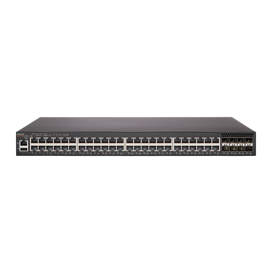
Hardware features..............................13 Hardware features The following sections describe the physical characteristics of the devices. ICX 7250 models The Ruckus ICX 7250 Ethernet switch is available in the models listed in the following table. TABLE 2 ICX 7250 models Model Description... -
Page 14: Network And Management Interfaces
USB port NOTE 24-port devices have similar front panels. For the ICX 7250-24G, the slot 2 ports are SFP ports. Console management interface The console management interface is a mini-USB port that allows you to configure and manage the device using a third-party terminal emulation application from a directly connected PC or through a terminal server. - Page 15 (data) ports. These ports support 1 Gbps but not 10 Gbps port speeds. All other Ruckus ICX 7250 devices contain eight SFP+ ports that support 1 Gbps or 10 Gbps port speeds. The top row ports are odd numbered (ports 1, 3, 5, and 7) and the bottom row ports are even numbered (ports 2, 4, 6, and 8). All ports can be used for stacking or uplinking.
- Page 16 The devices include LEDs that indicate the status of device components. NOTE The following figures show examples of the port status LEDs for similar ports are present for models with a higher number of ports. Ruckus ICX 7250 Switch Hardware Installation Guide Part Number: 53-1003898-08...
- Page 17 The PoE/PoE+ LEDs are reserved on models that do not support PoE or PoE+ operation. FIGURE 7 Port status LEDs for SFP or SFP+ ports SFP or SFP+ ports Bi-color status LED for upper port Bi-color status LED for lower port Ruckus ICX 7250 Switch Hardware Installation Guide Part Number: 53-1003898-08...
- Page 18 Not all models have all the LEDs and the location of the LEDs on the front panel may also be slightly different. FIGURE 8 System status LEDs on the ICX 7250-48P System status LEDs The following figure shows the system status LEDs for ICX 7250 models. Ruckus ICX 7250 Switch Hardware Installation Guide Part Number: 53-1003898-08...
- Page 19 Overview Hardware features FIGURE 9 System status LEDs for ICX 7250 models ICX 7250-24G LEDs ICX 7250-24, ICX 7250-24P, ICX 7250-48 LEDs ICX 7250-48P LEDs TABLE 5 System status LEDs Condition Status Green Power supply is operating normally. Yellow Power supply fault.
- Page 20 Ruckus ICX 7250-48 Ruckus ICX 7250-48P Power supply usage The Ruckus ICX 7250 models support specific AC power supply inputs and a number of PoE and PoE+ ports with an internal power supply. Ruckus ICX 7250 Switch Hardware Installation Guide...
- Page 21 Ruckus ICX 7250-24G 44.4 Ruckus ICX 7250-24 57.6 Ruckus ICX 7250-24P 454.0 24 (class 3) 12 (class 4) Ruckus ICX 7250-48 69.5 Ruckus ICX 7250-48P 942.0 48 (class 3) 24 (class 4) Ruckus ICX 7250 Switch Hardware Installation Guide Part Number: 53-1003898-08...
- Page 22 Ruckus ICX 7250 Switch Hardware Installation Guide Part Number: 53-1003898-08...
-
Page 23: Installation
Shipping carton contents Ruckus ICX 7250 devices ship with all of the following items included in the shipping carton. When unpacking the device, verify that the contents of the shipping carton is complete, if any items are missing, contact the place of purchase. -
Page 24: Summary Of Installation Tasks
Make sure the rack housing the device is adequately secured to prevent it from becoming unstable or falling over. DANGER Mount the devices you install in a rack as low as possible. Place the heaviest device at the bottom and progressively place lighter devices above. Ruckus ICX 7250 Switch Hardware Installation Guide Part Number: 53-1003898-08... -
Page 25: Power Precautions
2 m (6.6 ft) of each device, and is powered from an independent circuit breaker. As with any equipment, a filter or surge suppressor is recommended. • Some combinations of intake and exhaust airflows may not be compatible with your environment. Ruckus ICX 7250 Switch Hardware Installation Guide Part Number: 53-1003898-08... -
Page 26: Rack Mount Installation Considerations
Mount the devices you install in a rack as low as possible. Place the heaviest device at the bottom and progressively place lighter devices above. Desktop installation Complete the following steps to install the ICX 7250 device on a desktop or other flat surface. The device you are installing might look different than the one in the following illustration. DANGER This equipment is suitable for mounting on concrete or other noncombustible surfaces only. -
Page 27: Installing The Device Into A Rack
This section describes the procedures you use to mount the device into a rack. The Ruckus ICX 7250 can be installed in a 2-post or 4-post rack. The device ships with a 2-post rack. To use the rack that ships with the product, refer to... - Page 28 The #6-32 sink-head screws are for front-mounting. Use the #8-32 screws for rear-mounting. FIGURE 12 Attaching the rack mounting brackets for the ICX 7250 Remove the two-post rack kit from the shipping carton. The kit contains four rack-mounting screws and four cage nuts.
- Page 29 Before mounting your device, review any specific installation and facility requirements in this Hardware Installation Guide. • Hardware devices illustrated in these procedures are only for reference and may not depict the device you are installing into the rack. Ruckus ICX 7250 Switch Hardware Installation Guide Part Number: 53-1003898-08...
- Page 30 #2 Phillips torque screwdriver • 1/4-inch slotted-blade torque screwdriver Parts list The following parts are provided with the 1U, 1.5U, and 2U Universal Kit for Four Post Racks Installation (XBR-R000295). Ruckus ICX 7250 Switch Hardware Installation Guide Part Number: 53-1003898-08...
- Page 31 The device must be turned off and disconnected from the fabric during this procedure. NOTE Illustrations in these rack installation procedures are for reference only and may not show the actual device that you are installing. Ruckus ICX 7250 Switch Hardware Installation Guide Part Number: 53-1003898-08...
- Page 32 Use the upper and lower screw holes, leaving the center holes empty. Repeat Step 1 Step 2 to attach the left front bracket to the left side of the device. Ruckus ICX 7250 Switch Hardware Installation Guide Part Number: 53-1003898-08...
- Page 33 Use the upper and lower screw holes, leaving the center holes empty. Repeat step 1 and step 2 to attach the left bracket extension to the left side of the device. Ruckus ICX 7250 Switch Hardware Installation Guide Part Number: 53-1003898-08...
- Page 34 Attach the left front bracket to the left front rack post using two 10-32 x 5/8-in. panhead screws and two retainer nuts. Use the upper and lower holes in the bracket. Ruckus ICX 7250 Switch Hardware Installation Guide Part Number: 53-1003898-08...
- Page 35 Attach the brackets using four 6-32 x 1/4-in. panhead screws. Repeat Step 2 Step 3 to attach the left rear bracket to the left extension. Ruckus ICX 7250 Switch Hardware Installation Guide Part Number: 53-1003898-08...
- Page 36 FIGURE 18 Attaching the short rear brackets to the extensions Rear brackets Screws, 6-32 x 1/4-in., panhead Phillips FIGURE 19 Attaching the medium or long rear brackets to the extensions Ruckus ICX 7250 Switch Hardware Installation Guide Part Number: 53-1003898-08...
- Page 37 Retainer nuts, 10-32 Flush-rear (recessed) mounting the device in the rack The flush-rear (recessed) mounting is similar to the flush-front mounting except that the brackets are reversed on the device. Ruckus ICX 7250 Switch Hardware Installation Guide Part Number: 53-1003898-08...
- Page 38 Use the upper and lower screw holes, leaving the center holes empty. Repeat Step 1 Step 2 to attach the left front bracket to the left rear side of the device. Ruckus ICX 7250 Switch Hardware Installation Guide Part Number: 53-1003898-08...
- Page 39 Use the upper and lower screw holes, leaving the center holes empty. Repeat step 1 and step 2 to attach the left front bracket extension to the left side of the device. Ruckus ICX 7250 Switch Hardware Installation Guide Part Number: 53-1003898-08...
- Page 40 Attach the left front bracket to the left rear rack post using two 10-32 x 5/8-in. panhead screws and two retainer nuts. Use the upper and lower holes in the bracket. Ruckus ICX 7250 Switch Hardware Installation Guide Part Number: 53-1003898-08...
- Page 41 Attach the brackets using four 6-32 x 1/4-in. panhead screws. Repeat Step 2 Step 3 to attach the left rear bracket to the left extension. Ruckus ICX 7250 Switch Hardware Installation Guide Part Number: 53-1003898-08...
- Page 42 Adjust the brackets to the rack depth and tighten all the 6-32 x 1/4-in. screws to a torque of 9 in-lb (10 cm-kg). FIGURE 24 Attaching the short rear brackets to the extensions at the front of the device Rear brackets, short Screws, 6-32 x 1/4-in., panhead Phillips Ruckus ICX 7250 Switch Hardware Installation Guide Part Number: 53-1003898-08...
- Page 43 Attach the left rear bracket to the left front rack post using two 10-32 x 5/8-in. screws and two retainer nuts. Use the upper and lower holes in the bracket. Ruckus ICX 7250 Switch Hardware Installation Guide Part Number: 53-1003898-08...
- Page 44 NOTE Although this document describes how to install both single height (1U) and double height (2U) switches, the illustrations show a 1U switch as a typical installation. Ruckus ICX 7250 Switch Hardware Installation Guide Part Number: 53-1003898-08...
- Page 45 The illustrations in the rack installation procedures show a 1U device, but the instructions are the same for a 2U device. The illustrations in the rack installation procedures are for reference only and may not show the actual device. Ruckus ICX 7250 Switch Hardware Installation Guide Part Number: 53-1003898-08...
- Page 46 Tighten all the 8-32 x 5/16-in. screws to a torque of 15 in-lb (17 cm-kg). FIGURE 27 Attaching the front brackets The Ruckus ICX device Screws, 8-32 x 5/16-in., flathead Phillips Front brackets Ruckus ICX 7250 Switch Hardware Installation Guide Part Number: 53-1003898-08...
- Page 47 Attach the left front bracket to the left front rack post using two 10-32 x 5/8-in. panhead screws and two retainer nuts. Use the upper and lower holes in the bracket. Ruckus ICX 7250 Switch Hardware Installation Guide Part Number: 53-1003898-08...
- Page 48 If possible, leave at least one empty vertical pair of holes between the screws for better support. Repeat step 2 to attach the left rear bracket to the left extension. Ruckus ICX 7250 Switch Hardware Installation Guide Part Number: 53-1003898-08...
- Page 49 Attach the left rear bracket to the left rear rack post using two 10-32 x 5/8-in. panhead screws and two retainer nuts. Use the upper and lower holes in the bracket. Ruckus ICX 7250 Switch Hardware Installation Guide Part Number: 53-1003898-08...
- Page 50 52 Attaching the rear brackets to the extensions at the front of the device on page 53 Attaching the rear brackets to the front rack posts on page 55 Ruckus ICX 7250 Switch Hardware Installation Guide Part Number: 53-1003898-08...
- Page 51 Figure Attach the bracket using four 8-32 x 5/16-in. flathead screws. Repeat step 1 and step 2 to attach the left front extension to the left side of the device. Ruckus ICX 7250 Switch Hardware Installation Guide Part Number: 53-1003898-08...
- Page 52 Attach the left front bracket to the left rear rack post using two 10-32 x 5/8-in. panhead screws and two retainer nuts. Use the upper and lower holes in the bracket. Ruckus ICX 7250 Switch Hardware Installation Guide Part Number: 53-1003898-08...
- Page 53 Attach the brackets using four 6-32 x 1/4-in. screws. Repeat step 2 and step 3 to attach the left rear bracket to the left extension. Ruckus ICX 7250 Switch Hardware Installation Guide Part Number: 53-1003898-08...
- Page 54 FIGURE 35 Attaching the rear brackets to the extensions at the front of the device Rear brackets, short Screws, 6-32 x 1/4-in., panhead Phillips FIGURE 36 Attaching the short or long rear brackets to the extensions Ruckus ICX 7250 Switch Hardware Installation Guide Part Number: 53-1003898-08...
-
Page 55: Wall Mount Installation
You need a #2 Phillips screwdriver, a hammer, and a drill for wall mount installation. Ruckus recommends that you wall mount the device with the port side down. Complete the following steps to mount the device to a wall. Ruckus ICX 7250 Switch Hardware Installation Guide Part Number: 53-1003898-08... - Page 56 FIGURE 38 Attaching the wall mount brackets Drill two holes on the wall where you want to mount the device. Hammer two wall mount anchors into the holes on the wall. Ruckus ICX 7250 Switch Hardware Installation Guide Part Number: 53-1003898-08...
-
Page 57: Connecting Devices In A Traditional Stack
Connecting devices in a traditional stack ICX 7250 devices can operate as standalone devices and also as members of traditional stacks. A stack is a group of devices— Ruckus stackable units and their connected stacking links—that are connected so that the stack is managed as a single entity. -
Page 58: Stacking Ports And Trunks
Stacking ports and trunks There are eight SFP+ ports on the front panels of the ICX 7250 devices that support stacking, which can be used as uplink (data) ports or as stacking ports. The following figure shows the ports in slot 2; the top row consists of ports 1, 3, 5, and 7, and the bottom row consists of ports 2, 4, 6, and 8. - Page 59 The closed-loop connection provides a redundant path for the stack link, so if one link fails, stack communications can be maintained. FIGURE 42 Ring stacking topology First device in stack Second device in stack Ruckus ICX 7250 Switch Hardware Installation Guide Part Number: 53-1003898-08...
-
Page 60: Powering On The System
10G LRM SFP+ Optic, 1-pack bundle with LRM adapter; includes a rack-mount bracket. 10G-SFPP-LRM-2-ADP 10G LRM SFP+ Optic, 2-pack bundle with LRM adapter; includes rack- mount brackets. RMK-LRM-ADP 19-inch LRM Adapter Rack Mount Shelf Kit (supports 8 units). Ruckus ICX 7250 Switch Hardware Installation Guide Part Number: 53-1003898-08... -
Page 61: Lrm Adaptor Module Specifications
Two integrated Twinax cables for power and data connectivity to the host switch • Each port can operate at either 1Gbps or 10Gbps LEDs On the LRM adaptor module, two LEDs indicate the power status and link status of each connection. Ruckus ICX 7250 Switch Hardware Installation Guide Part Number: 53-1003898-08... -
Page 62: Icx Platform Support For The Lrm Adaptor Module
Note: On the ICX7750-48F, the connections must be distributed across the SFP+ ports as follows: • Maximum three LRM modules on ports 1/1/1 to 1/1/32 • Maximum three LRM modules on ports 1/1/33 to 1/1/48 Ruckus ICX 7250 Switch Hardware Installation Guide Part Number: 53-1003898-08... - Page 63 • One or two L-shaped mounting bracket (depending on the model purchased) • One or two 10G-SFPP-LRM optics (depending on the model purchased) • China-RoHS Hazardous and Toxic Substance statement Ruckus ICX 7250 Switch Hardware Installation Guide Part Number: 53-1003898-08...
- Page 64 Ruckus ICX 7250 Switch Hardware Installation Guide Part Number: 53-1003898-08...
- Page 65 In the event of an AC power loss or internal power supply device failure, the Ruckus EPS4000 external power supply can be used as a 12 V, backup power source to a device when any of the DC power supply ports are connected to an ICX 7250 device. The EPS4000 requires a minimum of one RPS17 Power Supply Unit (PSU) to be functional.
- Page 66 DC for use by the switches. NOTE The internal power supply of the ICX 7250 devices is not a field-replaceable unit (FRU). The devices must be shut down by administrators for replacement. Ruckus recommends that you pay attention to the PoE or PoE+ port configuration of the device when connecting to an EPS4000.
- Page 67 DC power cable connector 3 DC power cable connector 4 DC power cable connector 5 DC power cable connector 6 DC power cable connector 7 DC power cable connector 8 Ruckus ICX 7250 Switch Hardware Installation Guide Part Number: 53-1003898-08...
- Page 68 Switch is connected to this channel but EPS does not have sufficient 12 V backup power for this channel. Blinking amber This channel had a fault (for example, over current). CONFIG Green Auto-configuration mode. Amber Manual configuration mode. Ruckus ICX 7250 Switch Hardware Installation Guide Part Number: 53-1003898-08...
-
Page 69: Eps4000 External Power Supply
China ROHS sheet • Read Me First document Configuration requirements The configuration requirements for the EPS4000 are the same as the for the ICX 7250. Refer to Configuration requirements page 23. Summary of installation tasks Follow the steps in the following table to install your device. Details for each of these steps are provided on the pages indicated. -
Page 70: Installation Precautions
Compare this total with the rating limit for the circuit. The maximum ampere ratings are usually printed on the devices near the input power connectors. DANGER Disconnect the power cord from all power sources to completely remove power from the device. Ruckus ICX 7250 Switch Hardware Installation Guide Part Number: 53-1003898-08... -
Page 71: Preparing The Installation Site
You can install the device on a desktop or in an equipment rack. DANGER Mount the devices you install in a rack as low as possible. Place the heaviest device at the bottom and progressively place lighter devices above. Ruckus ICX 7250 Switch Hardware Installation Guide Part Number: 53-1003898-08... - Page 72 Mounting an external power supply in a rack (two-post) DANGER Make sure the rack housing the device is adequately secured to prevent it from becoming unstable or falling over. Ruckus ICX 7250 Switch Hardware Installation Guide Part Number: 53-1003898-08...
- Page 73 Using a Phillips screwdriver, attach the mounting brackets to the sides of the external power supply using 3 sink-head screws on each side. FIGURE 49 Attaching the mounting brackets to the device Mount the external power supply in a rack using four rack-mounting screws. Ruckus ICX 7250 Switch Hardware Installation Guide Part Number: 53-1003898-08...
-
Page 74: Installing An Rps17 Psu
You can install a new RPS17 Power Supply Unit (PSU) into EPS4000 while the device is powered on and running. NOTE While installing a PSU, wear an ESD wrist strap. DANGER For safety reasons, the ESD wrist strap should contain a series 1 megaohm resistor. Ruckus ICX 7250 Switch Hardware Installation Guide Part Number: 53-1003898-08... -
Page 75: Uninstalling An Rps17 Psu
Perform the following steps to uninstall an RPS17 PSU. Put on the ESD wrist strap and ground yourself by attaching the clip end to a metal surface (such as an equipment rack) to act as ground. Ruckus ICX 7250 Switch Hardware Installation Guide Part Number: 53-1003898-08... -
Page 76: Connecting The Eps4000 Cord
370 W at 54 V to each of two switches from one port on the EPS4000 power supply. Both cords deliver up to 120 W at 12 V. You must use a 1:2 cord if you want an ICX 7250-48P device to share 54-V power with another device. Both 1:1 and 1:2 cords will deliver only 370 W of 54 V power to an ICX 7250-24P device. - Page 77 Complete the following steps to connect the EPS4000 cord. CAUTION Do not use the cable to connect two EPS4000 ports. NOTE You can connect either end of the cable first. Hot insertion is supported for cable installation. Ruckus ICX 7250 Switch Hardware Installation Guide Part Number: 53-1003898-08...
-
Page 78: Powering On The System
The device shown in the diagram may be different from the one you are using. The process to remove the EPS4000 faceplate is the same. FIGURE 54 Removing the EPS4000 faceplate on the ICX 7250 device Faceplate screws Using a Phillips screwdriver, remove the two screws on the EPS4000 faceplate of the external power receptacle. -
Page 79: Verifying Proper Operation
1U; 19-inch rack-mountable or desktop Power inlet C14 for AC power Power outlet Custom connector for DC power to all ICX 7250 devices except ICX 7250-24G Power supply unit (PSU) Up to four RPS17, field-replaceable units (FRU) Fans One fan per installed RPS17... - Page 80 8.35 kg 1.72 inches 17.2 inches 16.0 inches 10.7 lb 18.4 lb Environmental requirements Condition Operational Non-operational Ambient temperature -5°C to 50°C (23°F to 122°F) -25°C to 70°C (-13°F to 158°F) Ruckus ICX 7250 Switch Hardware Installation Guide Part Number: 53-1003898-08...
- Page 81 30/2011/TT-BCT - Vietnam circular • SJ/T 11363-2006 Requirements for Concentration Limits for Certain Hazardous Substances in EIPs (China) • SJ/T 11364-2006 Marking for the Control of Pollution Caused by EIPs (China) Ruckus ICX 7250 Switch Hardware Installation Guide Part Number: 53-1003898-08...
- Page 82 Ruckus ICX 7250 Switch Hardware Installation Guide Part Number: 53-1003898-08...
- Page 83 You can access the CLI by attaching a serial cable to the console port. After you assign an IP address, you can access the system through Telnet or Brocade Network Advisor. Ruckus ICX 7250 Switch Hardware Installation Guide Part Number: 53-1003898-08...
-
Page 84: Password Assignment
CONFIG: The configuration level. This level allows you to configure the system IP address and configure switching and routing features. To access the CONFIG mode, you must already be logged in to the privileged EXEC level. Ruckus ICX 7250 Switch Hardware Installation Guide Part Number: 53-1003898-08... - Page 85 Depending on the device you purchased, and the code (Layer 2 or Layer 3) loaded on your system, the router prompt is displayed accordingly. For example, for an ICX 7250-48P device running Layer 3 code on the device, the router prompt displays ICX 7250-48P Router>...
-
Page 86: Ip Address Configuration
Access the global configuration level of the CLI by entering the following command: device# configure terminal Configure the IP address and mask for the device. device(config)# ip address 10.22.3.44 255.255.255.0 Ruckus ICX 7250 Switch Hardware Installation Guide Part Number: 53-1003898-08... - Page 87 Use the secondary option of the ip address command parameter if you have already configured an IP address within the same subnet on the interface. Configuring IP parameters for devices running Layer 3 software You must configure IP parameters for devices running Layer 3 software. Ruckus ICX 7250 Switch Hardware Installation Guide Part Number: 53-1003898-08...
- Page 88 A virtual interface is a logical port associated with a Layer 3 Virtual LAN (VLAN) configured on a Layer 3 device. You can configure routing parameters on the virtual interface to enable the Layer 3 device to route protocol traffic from one Layer 3 VLAN to the other, without using an external router. Ruckus ICX 7250 Switch Hardware Installation Guide Part Number: 53-1003898-08...
-
Page 89: Connecting Network Devices
The 802.3ab standard (automatic MDI or MDIX detection) calls for automatic negotiation of the connection between two 1000Base-T ports. In this case, a straight-through cable may work just as well as a crossover cable. For more information, refer to the FastIron Ethernet Switch Administration Guide. Ruckus ICX 7250 Switch Hardware Installation Guide Part Number: 53-1003898-08... - Page 90 Fiber cabling is required for direct attachment to Gigabit NICs or switches and routers through fiber ports. Refer to Connecting a network device to a fiber port on page 91. Ruckus ICX 7250 Switch Hardware Installation Guide Part Number: 53-1003898-08...
-
Page 91: Troubleshooting Network Connections
If the other procedures do not resolve the problem, try using a different port or a different cable. • If a 1-Gbps optic transceiver is inserted into an ICX 7250 device, you must configure the port using the speed-duplex 1000-full-master command at the interface level. -
Page 92: Testing Connectivity
Verify that the connection to the other network device has been properly made. • If the other actions do not resolve the problem, try using a different port or a different cable. Ruckus ICX 7250 Switch Hardware Installation Guide Part Number: 53-1003898-08... - Page 93 The CLI displays trace route information for each hop as soon as the information is received. Traceroute requests display all responses to a given TTL. In addition, if there are multiple equal-cost routes to the destination, the Ruckus device displays up to two responses by default. Ruckus ICX 7250 Switch Hardware Installation Guide Part Number: 53-1003898-08...
- Page 94 Ruckus ICX 7250 Switch Hardware Installation Guide Part Number: 53-1003898-08...
- Page 95 Integrated AC power supply for system and PoE power External AC power supply (EPS4000) for redundant system power and extended PoE/PoE+ power (not applicable to the ICX 7250-24G). DC power supplied to the switches depends on the EPS4000 configuration. Fans...
- Page 96 The following LEDs are not available on the ICX 7250-24G. EPS1: Bicolor LED (green/amber) indicates if the external power supply (EPS1) is operating normally EPS2 (available only on the ICX 7250-48P): Bicolor LED (green/amber) indicates if the external power supply (EPS2) is operating normally...
- Page 97 Power supply specifications (per PSU) The EPS4000 and its power supply modules (RPS17) are field-replaceable. All other Ruckus ICX 7250 power supply units (PSUs) are fixed and internal to the devices. All the PSUs use a C14 inlet and connect to standard AC power.
- Page 98 Power consumption (idle configuration) Idle: No optics or connections to ports installed and system booted up. Fans at nominal speed. NOTE The Ruckus ICX 7250 does not support -48 VDC input power. Model name @100 VAC input @200 VAC input...
- Page 99 Typical: 10% traffic rate on all ports with 64-byte packet size and random payload at room temperature. All ports fully configured. Fans at nominal speed. NOTE The Ruckus ICX 7250 does not support -48 VDC input power. Model name @100 VAC input...
- Page 100 NOTE The ICX 7250 10G ports provide a combination of active and passive cable support. Ports 1/2/1 to 1/2/4 can only be used with active cables when used for uplinks and either passive or active when used for stacking. Ports 1/2/5 to 1/2/8 can be used with either active or passive cable for any connection type.
- Page 101 2 x 8 MB Compact Flash NAND 2 GB Main DDR3 (onboard IC) ICX 7250-24G: 1 GB ICX 7250-24: 2 GB ICX 7250-24P: 2 GB ICX 7250-48: 2 GB ICX 7250-48P: 2 GB Ruckus ICX 7250 Switch Hardware Installation Guide Part Number: 53-1003898-08...
- Page 102 30/2011/TT-BCT - Vietnam circular. • SJ/T 11363-2006 Requirements for Concentration Limits for Certain Hazardous Substances in EIPs (China). • SJ/T 11364-2006 Marking for the Control of Pollution Caused by EIPs (China). Ruckus ICX 7250 Switch Hardware Installation Guide Part Number: 53-1003898-08...
-
Page 103: Danger
NOTE Effective November 30, 2018, the Brocade Network Advisor for managing Ruckus switches and Access Points have gone End of Sale. We recommend that you use Ruckus SmartZoneOS 5. Ruckus ICX 7250 Switch Hardware Installation Guide Part Number: 53-1003898-08... - Page 104 (refer to the following table). If the Ruckus ICX 7250 determines that there is a problem with the fans, it performs the following actions and generates the following syslog messages, as shown in the following table.
- Page 105 Managing an ICX 7250 Device Managing temperature settings TABLE 18 Ruckus ICX 7250 fan error detection and resolution Issue detected Attempted resolution During system bootup, no fan is detected The system immediately shuts down. During system bootup, fewer fans than required...
- Page 106 The following console and syslog message is displayed when the temperature reaches the warning level: !!! Temperature is over warning level on stack unit 1!!! Ruckus ICX 7250 Switch Hardware Installation Guide Part Number: 53-1003898-08...
- Page 107 Use the clear mac-address ethernet port-num command to remove all MAC addresses for a specified Ethernet port. Use the clear mac-address vlan number command to remove all MAC addresses for a specified VLAN. Ruckus ICX 7250 Switch Hardware Installation Guide Part Number: 53-1003898-08...
- Page 108 Ruckus ICX 7250 Switch Hardware Installation Guide Part Number: 53-1003898-08...
- Page 109 Removing a copper or fiber-optic module You can remove a copper or fiber SFP or SFP+ transceiver from a slot while the ICX 7250 device is powered on and running. While removing a copper or fiber-optic module, be sure to wear an ESD wrist strap with a plug that can be inserted in the ESD connector on the ICX 7250 device.
- Page 110 You can install a new fiber-optic transceiver in an SFP or SFP+ slot while the device is powered on and running. While installing a transceiver, wear an ESD wrist strap with a plug that can be inserted in the ESD connector on the ICX 7250 device.
- Page 111 Before cabling a fiber-optic transceiver, Ruckus strongly recommends cleaning the cable connectors and the port connectors. Gently insert the cable connector (a tab on each connector should face upward) into the transceiver connector until the tabs lock into place. Ruckus ICX 7250 Switch Hardware Installation Guide Part Number: 53-1003898-08...
- Page 112 Observe the link and active LEDs to determine if the network connections are functioning properly. For more information about the LED indicators, refer to Observing LEDs on page 92. Ruckus ICX 7250 Switch Hardware Installation Guide Part Number: 53-1003898-08...
- Page 113 If you still cannot isolate the problem, then the internal power supply may be defective. In this case, contact Ruckus Technical Support for assistance. Ruckus ICX 7250 Switch Hardware Installation Guide Part Number: 53-1003898-08...
- Page 114 IP address. Also, be sure the port through which you are connecting to the device has not been disabled. If it has not been disabled, then check the network cabling that runs between your remote location and the device. Ruckus ICX 7250 Switch Hardware Installation Guide Part Number: 53-1003898-08...
- Page 115 BSMI statement (Taiwan) Warning: This is Class A product. In a domestic environment this product may cause radio interference in which case the user may be required to take adequate measures. Ruckus ICX 7250 Switch Hardware Installation Guide Part Number: 53-1003898-08...
-
Page 116: Bsmi Statement (Taiwan)
Regulatory Statements BSMI statement (Taiwan) Ruckus ICX 7250 Switch Hardware Installation Guide Part Number: 53-1003898-08... -
Page 117: Canadian Requirements
This Class A digital apparatus meets all requirements of the Canadian Interference-Causing Equipment Regulations, ICES-003 Class A. Cet appareil numérique de la classe A est conforme à la norme NMB-003 du Canada. Ruckus ICX 7250 Switch Hardware Installation Guide Part Number: 53-1003898-08... -
Page 118: China Ccc Statement
Europe and Australia (CISPR 32 Class A Warning) This is a Class A product. In a domestic environment this product may cause radio interference in which case the user may be required to take adequate measures. Ruckus ICX 7250 Switch Hardware Installation Guide Part Number: 53-1003898-08... -
Page 119: Fcc Warning (Us Only)
This is a Class A product based on the standard of the Voluntary Control Council for Interference by Information Technology Equipment (VCCI). If this equipment is used in a domestic environment, radio disturbance might arise. When such trouble occurs, the user might be required to take corrective actions. Ruckus ICX 7250 Switch Hardware Installation Guide Part Number: 53-1003898-08... - Page 120 Ruckus ICX 7250 Switch Hardware Installation Guide Part Number: 53-1003898-08...
- Page 121 MISE EN GARDE Assurez-vous que le circuit est correctement ventilé. Il est recommandé de conserver un espace de 3 cm au-dessus du dispositif, et de 8 cm sur chaque côté. Ruckus ICX 7250 Switch Hardware Installation Guide Part Number: 53-1003898-08...
- Page 122 PRECAUCIÓN Use un circuito derivado separado para cada cordón de alimentación, con lo que se proporcionará redundancia en caso de que uno de los circuitos falle. Ruckus ICX 7250 Switch Hardware Installation Guide Part Number: 53-1003898-08...
- Page 123 Ein Gefahrenhinweis warnt vor Bedingungen oder Situationen die tödlich sein können oder Sie extrem gefährden können. Sicherheitsetiketten sind direkt auf den jeweiligen Produkten angebracht um vor diesen Bedingungen und Situationen zu warnen. Ruckus ICX 7250 Switch Hardware Installation Guide Part Number: 53-1003898-08...
- Page 124 Avant de commencer l'installation, consultez les précautions décrites dans “Power Precautions” (Précautions quant à l'alimentation). PELIGRO Antes de comenzar la instalación, consulte las precauciones en la sección “Power Precautions” (Precauciones sobre corriente). Ruckus ICX 7250 Switch Hardware Installation Guide Part Number: 53-1003898-08...
- Page 125 Vérifiez que le bâti abritant le dispositif est bien fixé afin qu'il ne devienne pas instable ou qu'il ne risque pas de tomber. PELIGRO Verifique que el bastidor que alberga el instrumento está asegurado correctamente para evitar que pueda hacerse inestable o que caiga. Ruckus ICX 7250 Switch Hardware Installation Guide Part Number: 53-1003898-08...
- Page 126 Alle Glasfaser-Schnittstellen verwenden Laser der Klasse 1. DANGER Toutes les interfaces en fibre optique utilisent des lasers de classe 1. PELIGRO Todas las interfaces de fibra óptica utilizan láser de clase 1. Ruckus ICX 7250 Switch Hardware Installation Guide Part Number: 53-1003898-08...
- Page 127 © 2019 ARRIS Enterprises LLC. All rights reserved. Ruckus Wireless, Inc., a wholly owned subsidiary of ARRIS International plc. 350 West Java Dr., Sunnyvale, CA 94089 USA www.ruckuswireless.com...
Need help?
Do you have a question about the ICX 7250 and is the answer not in the manual?
Questions and answers