
Subscribe to Our Youtube Channel
Related Manuals for Ruckus Wireless ICX 7850 Series


Summary of Contents for Ruckus Wireless ICX 7850 Series
- Page 1 HARDWARE INSTALLATION GUIDE Ruckus ICX 7850 Switch Hardware Installation Guide Part Number: 53-1005580-01 Publication Date: 01 March 2019...
- Page 2 Ruckus Wireless, Ruckus, the bark logo, BeamFlex, ChannelFly, Dynamic PSK, FlexMaster, ICX, Simply Better Wireless, SmartCell, SmartMesh, SmartZone, Unleashed, ZoneDirector and ZoneFlex are trademarks of Ruckus Wireless, Inc. in the United States and in other countries. Other trademarks may belong to third parties.
-
Page 3: Table Of Contents
Contents Preface ................. . . vii Document Conventions . - Page 4 ............17 Two-Post Rack Mount Installation (ICX-RMK-4POST-TL) .
- Page 5 ................. . 62 Time and Items Required .
- Page 6 Ruckus ICX 7850 Switch Hardware Installation Guide Part Number: 53-1005580-01...
-
Page 7: Preface
Preface • Document Conventions................vii •... -
Page 8: Document Feedback
Document Feedback Convention Description Boldface text Identifies command names, keywords, and command options. Italic text Identifies a variable. Syntax components displayed within square brackets are optional. Default responses to system prompts are enclosed in square brackets. { x | y | z } A choice of required parameters is enclosed in curly brackets separated by vertical bars. -
Page 9: Contacting Ruckus Customer Services And Support
Contacting Ruckus Customer Services and Support Contacting Ruckus Customer Services and Support The Customer Services and Support (CSS) organization is available to provide assistance to customers with active warranties on their Ruckus products, and customers and partners with active support contracts. For product support information and details on contacting the Support Team, go directly to the Support Portal using https:// support.ruckuswireless.com, or go to... - Page 10 Contacting Ruckus Customer Services and Support Ruckus ICX 7850 Switch Hardware Installation Guide Part Number: 53-1005580-01...
-
Page 11: About This Document Supported Hardware And Software
About This Document • Supported Hardware and Software..............1 Supported Hardware and Software This document is applicable for the various Ruckus ICX 7850 switch models. - Page 12 About This Document Supported Hardware and Software Ruckus ICX 7850 Switch Hardware Installation Guide Part Number: 53-1005580-01...
-
Page 13: Device Overview
Device Overview • Hardware Features ..................3 •... -
Page 14: Port-Side Views Of The Ruckus Icx 7850 Switch
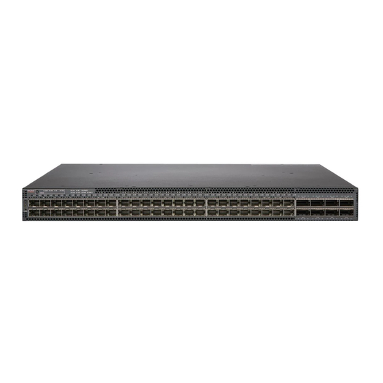
Device Overview Port-side Views of the Ruckus ICX 7850 Switch Port-side Views of the Ruckus ICX 7850 Switch Figure 1 shows the front view of the Ruckus ICX 7850-32Q switch. FIGURE 1 Front View of the Ruckus ICX 7850-32Q Status mode button Reset button Status mode LEDs USB port (for flash drive) -
Page 15: Nonport-Side View Of The Ruckus Icx 7850 Switch
Device Overview Nonport-side View of the Ruckus ICX 7850 Switch FIGURE 3 Front View of the Ruckus ICX 7850-48FS Status mode button Reset button Status mode LEDs Slot 1: 1/10 GbE SFP+ ports (MACSec capable) System LEDs Slot 2: 40/100 GbE QSFP28 stacking/uplink ports USB Type-C console port Nonport-side View of the Ruckus ICX 7850 Switch Figure 4... -
Page 16: Device Management Options
Device Overview Device Management Options FIGURE 5 Rear View of the Ruckus ICX 7850-48F and ICX 7850-48FS Power supply unit 2 Fan assembly 2 Fan assembly 5 Fan assembly 1 Fan assembly 4 Power supply unit 1 Fan assembly 3 10 Grounding terminal RJ-45 console port 11 Management port (RJ-45) -
Page 17: Preparing For Installation Safety Precautions
Preparing for Installation • Safety Precautions ..................7 •... -
Page 18: Esd Precautions
Preparing for Installation Safety Precautions CAUTION To protect the serial port from damage, keep the cover on the port when not in use. CAUTION Never leave tools inside the chassis. CAUTION If you do not install a module or a power supply in a slot, you must keep the slot filler panel in place. If you run the chassis with an uncovered slot, the system will overheat. -
Page 19: Lifting Precautions
Preparing for Installation Safety Precautions DANGER Disconnect the power cord from all power sources to completely remove power from the device. DANGER This device might have more than one power cord. To reduce the risk of electric shock, disconnect all power cords before servicing. -
Page 20: Facility Requirements
Preparing for Installation Facility Requirements DANGER Laser radiation. Do not view directly with optical instruments. Class 1M laser products. DANGER Use only optical transceivers that are qualified by Ruckus and comply with the FDA Class 1 radiation performance requirements defined in 21 CFR Subchapter I, and with IEC 60825 and EN60825. Optical products that do not comply with these standards might emit light that is hazardous to the eyes. -
Page 21: Rack Considerations
Preparing for Installation Facility Requirements • Allow for twisted-pair cables to be routed away from power lines, fluorescent lighting fixtures, and other sources of electrical interference, such as radios and transmitters. • Allow for the unit to be connected to a separate grounded power outlet that provides 100 to 240 VAC, 50 to 60 Hz, is within 2 m (6.6 ft) of each device, and is powered from an independent circuit breaker. -
Page 22: Quick Installation Checklist
Preparing for Installation Quick Installation Checklist Quick Installation Checklist This checklist provides a high-level overview of the basic installation process from the planning stage to the point where the device comes online and is ready to be deployed. Completing all the tasks in the suggested order ensures successful installation. Ruckus recommends that you print this checklist and take it to the installation site. - Page 23 Preparing for Installation Shipping Carton Contents One US AC power cord, shielded (included only with devices with pre-installed power supplies. (E2 devices have two power cords.) One console cable (RJ-45 to RJ-45 crossover) One RJ-45-to-DB9 adapter Installed filler panels for the power supply slot or fan assembly slot where such modules are not supplied for the switch China ROHS sheet Read Me First document Ruckus ICX 7850 Switch Hardware Installation Guide...
- Page 24 Preparing for Installation Shipping Carton Contents Ruckus ICX 7850 Switch Hardware Installation Guide Part Number: 53-1005580-01...
-
Page 25: Mounting The Device
Mounting the Device • Mounting Options ..................15 •... -
Page 26: Installing The Device On A Desktop
Mounting the Device Installing the Device on a Desktop CAUTION Use the screws specified in the procedure. Using longer screws can damage the device. CAUTION Do not install the device in an environment where the operating ambient temperature might exceed 50°C (122°F). Installing the Device on a Desktop Complete the following steps to install the Ruckus ICX 7850 on a desktop or other flat surface. -
Page 27: Two-Post Rack Mount Installation (Icx-Rmk-4Post-Tl)
Mounting the Device Two-Post Rack Mount Installation (ICX-RMK-4POST-TL) Before mounting the switch in a rack, pay particular attention to the following factors: • Temperature: Because the temperature within a rack assembly may be higher than the ambient room temperature, check that the rack-environment temperature is within the specified operating temperature range. -
Page 28: Time And Items Required
Mounting the Device Two-Post Rack Mount Installation (ICX-RMK-4POST-TL) NOTE Use the following procedure when installing the Ruckus ICX 7850 in a two-post rack. For four-post racks, follow the procedures “Four-Post Rack Mount Installation (ICX-RMK-4POST-TL)” on page 20 or “Installing the 1U, 1.5U, and 2U Universal Kit for Four-Post Racks (XBR-R000295)”... -
Page 29: Flush-Front Mounting
Mounting the Device Two-Post Rack Mount Installation (ICX-RMK-4POST-TL) Flush-Front Mounting CAUTION The device must be turned off and disconnected from the fabric during this procedure. Complete the following tasks to install the device in a two-post rack. “Attaching the Front Brackets” on page 22 “Installing the Device in the Rack”... -
Page 30: Four-Post Rack Mount Installation (Icx-Rmk-4Post-Tl)
Mounting the Device Four-Post Rack Mount Installation (ICX-RMK-4POST-TL) Position the device in the rack, as shown in Figure 10, providing temporary support under the device until the rail kit is secured to the rack. Attach the right front bracket to the right front rack post using two 10-32 x 5/8-in. panhead screws and two retainer nuts. Use the upper and lower holes in the bracket. -
Page 31: Parts List
Mounting the Device Four-Post Rack Mount Installation (ICX-RMK-4POST-TL) Parts List The following parts are provided with the four-post flush-mount rack kit (ICX-RMK-4POST-TL). FIGURE 11 Items in the Four-Post Flush-Mount Rack Kit Front brackets (2) Screw, 10-32 x 5/8-in., panhead Phillips (12) Rear brackets (2) Retainer nut, 10-32 (12) Ensure that the items listed and illustrated in... - Page 32 Mounting the Device Four-Post Rack Mount Installation (ICX-RMK-4POST-TL) Attaching the Front Brackets Complete the following steps to attach the front brackets to the device. Position the right front bracket with the flat side against the right side of the device over the six pre-installed keyhole fasteners, as shown in Figure Slide the bracket toward the front of the device until the bracket latch clicks into its secure position.
- Page 33 Mounting the Device Four-Post Rack Mount Installation (ICX-RMK-4POST-TL) FIGURE 13 Positioning the Device in the Rack Screws, 10-32 x 5/8-in., panhead Phillips Retainer nuts, 10-32 Attaching the Rear Brackets to the Rack Posts Complete the following steps to attach the rear brackets to the rack posts. Slide the right rear bracket into the right front bracket and the left rear bracket into the left front bracket.
-
Page 34: Installing The 1U, 1.5U, And 2U Universal Kit For Four-Post Racks (Xbr-R000295)
Mounting the Device Installing the 1U, 1.5U, and 2U Universal Kit for Four-Post Racks (XBR-R000295) FIGURE 14 Attaching the Rear Brackets to the Rack Posts Screws, 10-32 x 5/8-in., panhead Phillips Retainer nuts, 10-32 Installing the 1U, 1.5U, and 2U Universal Kit for Four-Post Racks (XBR-R000295) Use the following instructions to install a Ruckus ICX 7850 switch in a 19-in. -
Page 35: Time And Items Required
Mounting the Device Installing the 1U, 1.5U, and 2U Universal Kit for Four-Post Racks (XBR-R000295) Time and Items Required Allow 15 to 30 minutes to complete this procedure. The following items are required to install the device using the 1U, 1.5U, and 2U Universal Kit for Four-Post Racks (XBR-R000295): •... - Page 36 Mounting the Device Installing the 1U, 1.5U, and 2U Universal Kit for Four-Post Racks (XBR-R000295) Complete the following tasks to install the device in a four-post rack. “Attaching the Front Brackets” on page 26 “Attaching the Extension Brackets to the Device” on page 27 “Installing the Device in the Rack”...
- Page 37 Mounting the Device Installing the 1U, 1.5U, and 2U Universal Kit for Four-Post Racks (XBR-R000295) Attaching the Extension Brackets to the Device Complete the following steps to attach the extension brackets to the device. There are medium and long extension brackets that you can use for this step.
- Page 38 Mounting the Device Installing the 1U, 1.5U, and 2U Universal Kit for Four-Post Racks (XBR-R000295) FIGURE 18 Positioning the Device in the Rack Screws, 10-32 x 5/8-in., panhead Phillips Retainer nuts, 10-32 Attaching the Rear Brackets to the Extensions Complete the following steps to attach the rear brackets to the extensions. There are short and long rear brackets that you can use for this step.
- Page 39 Mounting the Device Installing the 1U, 1.5U, and 2U Universal Kit for Four-Post Racks (XBR-R000295) FIGURE 19 Attaching the Rear Brackets to the Extensions Rear brackets Screws, 6-32 x 1/4-in., panhead Phillips FIGURE 20 Attaching the Medium or Long rear Brackets to the Extensions Rear bracket, medium or long Screws, 6-32 x 1/4-in., panhead Phillips Attaching the Rear Brackets to the Rack Posts...
-
Page 40: Flush-Rear (Recessed) Mounting The Device In The Rack
Mounting the Device Installing the 1U, 1.5U, and 2U Universal Kit for Four-Post Racks (XBR-R000295) FIGURE 21 Attaching the Rear Brackets to the Rack Posts Screws, 10-32 x 5/8-in., panhead Phillips Retainer nuts, 10-32 Flush-Rear (Recessed) Mounting the Device in the Rack The flush-rear (recessed) mounting is similar to the flush-front mounting except that the brackets are reversed on the device. - Page 41 Mounting the Device Installing the 1U, 1.5U, and 2U Universal Kit for Four-Post Racks (XBR-R000295) Attaching the Front Brackets to the Rear of the Device NOTE In this installation, the brackets are named as listed in the parts list even though the installation of the brackets is reversed from the flush-front installation.
- Page 42 Mounting the Device Installing the 1U, 1.5U, and 2U Universal Kit for Four-Post Racks (XBR-R000295) Tighten all the 8-32 x 5/16-in. screws to a torque of 15 in-lb (17 cm-kg). FIGURE 23 Attaching the Bracket Extensions to the Device Extension brackets Screws, 8-32 x 5/16-in., flathead Phillips Installing the Device in the Rack Complete the following steps to install the device in the rack.
- Page 43 Mounting the Device Installing the 1U, 1.5U, and 2U Universal Kit for Four-Post Racks (XBR-R000295) FIGURE 24 Positioning the Device in the Rack Screws, 10-32 x 5/8-in., panhead Phillips Retainer nuts, 10-32 Attaching the Rear Brackets to the Extensions at the Front of the Device Complete the following steps to attach the rear brackets to the extensions.
- Page 44 Mounting the Device Installing the 1U, 1.5U, and 2U Universal Kit for Four-Post Racks (XBR-R000295) FIGURE 25 Attaching the Rear Brackets to the Extensions at the Front of the Device Rear brackets, short Screws, 6-32 x 1/4-in., panhead Phillips FIGURE 26 Attaching the Medium or Long Rear Brackets to the Extensions Rear bracket, medium or long Screws, 6-32 x 1/4-in., panhead Phillips Attaching the Rear Brackets to the Front Rack Posts...
-
Page 45: Connecting Devices In A Stack
Mounting the Device Connecting Devices in a Stack Attach the right rear bracket to the right front rack post using two 10-32 x 5/8-in. screws and two retainer nuts, as shown in Figure 27. Use the upper and lower holes in the bracket. Attach the left rear bracket to the left front rack post using two 10-32 x 5/8-in. -
Page 46: Stacking Configuration Requirements
Mounting the Device Connecting Devices in a Stack FIGURE 28 Ruckus ICX 7850-32Q Stacking Ports The 100-GbE ports 1/3/1 and 1/3/5 are default stacking ports. Default stacking ports have the capability to accept special stacking packets during a CLI-initiated command sequence of the Secure Setup utility. The following figure shows the stacking ports on the Ruckus ICX 7850-48F and ICX 7850-48FS. -
Page 47: Stacking Cables
Mounting the Device Connecting Devices in a Stack Stacking Cables Use QSFP28 direct-attached copper stacking cables or QSFP28 optics with fiber cables to connect the Ruckus ICX 7850 devices in a stack. NOTE Stacking cables are not included in the shipping carton and must be ordered separately. Stack Size A traditional stack can contain a maximum of twelve Ruckus ICX 7850 devices that are any combination of 7850-32Q, 7850-48F, or 7850-48FS. -
Page 48: Interactive-Setup Utility
Mounting the Device Connecting Devices in a Stack FIGURE 31 100-GbE Ring Stacking Topology Interactive-Setup Utility Stack interactive-setup lets you easily configure your entire stack through the active controller, which propagates the configuration to all stack members. Stack interactive-setup is the most secure way to build a traditional stack and gives you the most control over how your stack is built. -
Page 49: Support For Two-Unit Stack Linear Trunks
Mounting the Device Connecting Devices in a Stack Support for Two-Unit Stack Linear Trunks FastIron release 08.0.90 and later releases support a linear-topology trunk in a two-unit stack. A two-unit stack can form a linear topology with a trunk containing all stacking ports, instead of dividing the ports into the two directions of a ring topology. The linear-topology trunk provides the same redundancy as a two-unit ring because of trunk load balancing. - Page 50 Mounting the Device Connecting Devices in a Stack Ruckus ICX 7850 Switch Hardware Installation Guide Part Number: 53-1005580-01...
-
Page 51: Initial Setup And Verification
Initial Setup and Verification • Providing Power to the Device ............... . 41 •... -
Page 52: Establishing An Out-Of-Band Management Port Connection
Initial Setup and Verification Establishing an Out-of-Band Management Port Connection Disable any serial communication programs running on the workstation such as synchronization programs. Open a terminal emulator application such as HyperTerminal on a Windows PC, or TERM, TIP, or Kermit in a UNIX environment, and configure the application as follows: •... -
Page 53: Installing Transceivers And Cables
Installing Transceivers and Cables • Precautions Specific to Transceivers and Cables ............43 •... -
Page 54: Managing Cables
Installing Transceivers and Cables Managing Cables Managing Cables Cables can be organized and managed in a variety of ways, for example, using cable channels on the sides of the rack or patch panels to minimize cable management. Follow these recommendations: NOTE You should not use tie wraps with optical cables because they are easily overtightened and can damage the optic fibers. -
Page 55: Replacing A Fiber-Optic Transceiver
Installing Transceivers and Cables Replacing a Fiber-Optic Transceiver DANGER Laser radiation. Do not view directly with optical instruments. Class 1M laser products. Use the following steps to install a transceiver. Put on the ESD wrist strap and ground yourself by attaching the clip end to a metal surface (such as an equipment rack) to act as ground. -
Page 56: Connecting Network Devices
Installing Transceivers and Cables Connecting Network Devices DANGER For safety reasons, the ESD wrist strap should contain a series 1 megohm resistor. Use the following steps to remove a fiber-optic transceiver from a slot. Put on the ESD wrist strap and ground yourself by attaching the clip end to a metal surface (such as an equipment rack). Disconnect the fiber cable connector from the port connector. - Page 57 Installing Transceivers and Cables Connecting Network Devices NOTE To verify that a Ruckus ICX 7850 switch can reach another device through the network, use the ping command at any level of the CLI. For more information, refer to the Ruckus FastIron Management Configuration Guide. Ruckus ICX 7850 Switch Hardware Installation Guide Part Number: 53-1005580-01...
- Page 58 Installing Transceivers and Cables Connecting Network Devices Ruckus ICX 7850 Switch Hardware Installation Guide Part Number: 53-1005580-01...
-
Page 59: Monitoring The Device
Monitoring the Device • LED Activity Interpretation ................49 •... - Page 60 Monitoring the Device Ruckus ICX 7850 Port-Side LEDs FIGURE 34 Ruckus ICX 7850-32Q Front-Panel LEDs Mode status LEDs: STAT, SPD, ID, USB Management port speed LED SYS (system status) and DIAG (diagnostic) status QSFP28 port 100/40 GbE or 4x25/10 GbE mode LEDs lane 1 link/activity LED MS (stacking configuration) status and CLD (cloud...
- Page 61 Monitoring the Device Ruckus ICX 7850 Port-Side LEDs Figure 35 shows the LEDs on the Ruckus ICX 7850-48F front panel. FIGURE 35 Ruckus ICX 7850-48F Front-Panel LEDs Mode status LEDs: STAT, SPD, ID, USB SFP28 ports 1-48 status LEDs SYS (system status) and DIAG (diagnostic) status QSFP28 port 100/40 GbE or 4x25/10 GbE mode LEDs lane 1 link/activity LED...
-
Page 62: Ruckus Icx 7850 Nonport-Side Leds
Monitoring the Device Ruckus ICX 7850 Nonport-Side LEDs FIGURE 36 Ruckus ICX 7850-48FS Front-Panel LEDs Mode status LEDs: STAT, SPD, ID, USB SFP+ ports 1-48 status LEDs SYS (system) and DIAG (diagnostic) status LEDs QSFP28 port 100/40 GbE or 4x25/10 GbE mode lane 1 link/activity LED MS (stacking configuration) status and CLD (cloud QSFP28 port 4x25/10 GbE mode lane 2... -
Page 63: Status Mode Button And Leds
Monitoring the Device Status Mode Button and LEDs Figure 37 shows the LEDs on the rear panel of the Ruckus ICX 7850-48F and ICX 7850-48FS. FIGURE 38 Ruckus ICX 7850-48F and ICX 7850-48FS Rear-Panel LEDs PSU2 input (lower) and output (upper) status LEDs 6 FAN1 fan assembly LED FAN5 fan assembly LED PSU1 input (lower) and output (upper) status LEDs... -
Page 64: Led Patterns
Monitoring the Device LED Patterns LED Patterns The following tables describe the Ruckus ICX 7850 LED patterns. TABLE 9 Management Port Left (Link/Activity) Status LED LED State Status of Hardware Recommended Action Off (no light) Not cabled or no link. No action required. - Page 65 Monitoring the Device LED Patterns TABLE 14 UPDATE LED LED State Status of Hardware Recommended Action Off (no light) System is running an earlier software image. No action required. Blinking green The switch software is being updated through DHCP, USB/TFTP, No action required.
- Page 66 Monitoring the Device LED Patterns TABLE 17 100 GbE, 40 GbE, 25 GbE, 10 GbE, 1 GbE Port Status LEDs (Continued) Status Mode LED State Status of Hardware Recommended Action Off (no light) No valid link on the port. No action required. Steady green Port is operating at its highest speed.
-
Page 67: Diagnostic Tests And Monitoring
Monitoring the Device Diagnostic Tests and Monitoring Diagnostic Tests and Monitoring Ruckus FastIron software includes diagnostic tests to help you troubleshoot the hardware. System diagnostic software is designed to fulfill the purpose of offline diagnostics. In offline diagnostics, you must turn the diagnostic flags on or off to execute diagnostic tests during the next bootup. - Page 68 Monitoring the Device Diagnostic Tests and Monitoring Ruckus ICX 7850 Switch Hardware Installation Guide Part Number: 53-1005580-01...
-
Page 69: Power Supplies
Power Supplies • Power Supply Overview ................59 •... -
Page 70: Precautions Specific To Power Supplies
Power Supplies Precautions Specific to Power Supplies FIGURE 39 AC Power Supply Release lever Power supply handle FIGURE 40 DC Power Supply Release lever Power supply handle Precautions Specific to Power Supplies DANGER Make sure that the power source circuits are properly grounded, then use the power cord supplied with the device to connect it to the power source. -
Page 71: Identifying The Airflow Direction
Power Supplies Identifying the Airflow Direction DANGER If the installation requires a different power cord than the one supplied with the device, make sure you use a power cord displaying the mark of the safety agency that defines the regulations for power cords in your country. The mark is your assurance that the power cord can be used safely with the device. -
Page 72: Time And Items Required
Power Supplies Time and Items Required • Exhaust power supply and fan assembly with a green "E" label: Pulls air from the port side of the switch and exhausts it out the nonport side. • Nonport-side air exhaust • Port-side air intake •... -
Page 73: Inserting A New Dc Power Supply
Power Supplies Inserting a New DC Power Supply FIGURE 41 Installing an AC Power Supply Unit Power supply slot Release lever If replacing a power supply, remove the previously installed power supply from the appropriate slot by pressing the release lever and pulling the power supply handle. - Page 74 Power Supplies Inserting a New DC Power Supply CAUTION Use a UL listed or CSA Certified DC power source to connect to a DC PSU. FIGURE 42 Installing a DC Power Supply Unit Release lever DC power supply terminals Make sure DC power is disconnected at the circuit breaker before proceeding. Prepare the power and safety grounding wires using the appropriate size wire.
-
Page 75: Grounding The Ruckus Icx 7850 Switch
Power Supplies Grounding the Ruckus ICX 7850 Switch FIGURE 43 DC Power Supply Wiring Terminals DC power terminals Safety ground screw Make sure the screws are tight with no wire touching the ground screw. 10. Using the handle on the power supply, hold the power supply level and guide it into the power supply slot. Gently push the power supply all the way into the slot, ensuring that it firmly engages with the connector and the release lever clicks into its locked position. - Page 76 Power Supplies Grounding the Ruckus ICX 7850 Switch CAUTION For the installation of a Ruckus device with AC or DC systems, use a ground wire of at least 10 AWG. The ground wire should have an agency-approved crimped connector (provided with the device) attached to one end, with the other end attached to building ground.
-
Page 77: Fan Assemblies
Fan Assemblies • Fan Assembly Overview ................67 •... -
Page 78: Precautions Specific To Fan Assemblies
Fan Assemblies Precautions Specific to Fan Assemblies Precautions Specific to Fan Assemblies DANGER Be careful not to accidentally insert your fingers into the fan assembly while removing it from the chassis. The fan may still be spinning at a high speed. CAUTION Disassembling any part of the power supply and fan assembly voids the warranty and regulatory certifications. -
Page 79: Time And Items Required
Fan Assemblies Time and Items Required Time and Items Required Installing or removing and replacing a fan assembly should require less than five minutes to complete. The following items are required to replace a fan assembly: • New fan assembly (must have the same airflow direction as the fan assembly being replaced) •... - Page 80 Fan Assemblies Inserting a New Fan Assembly If installing a new fan assembly into a slot covered with a filler panel: Using a Phillips screwdriver, unscrew the captive screw on the filler panel. Remove the filler panel. Before opening the package that contains the new fan assembly, touch the bag to the switch casing to discharge any potential static electricity.
-
Page 81: Ruckus Icx 7850 Specifications
Ruckus ICX 7850 Specifications • System Specifications ................71 •... -
Page 82: Leds
Ruckus ICX 7850 Specifications LEDs LEDs System Component Description Switch Status and Seven LED types indicate switch status: Management PWR and PWR2 (power supply units) DIAG (diagnostics) SYS (system status) MS (stacking configuration) CLD (cloud management) UPDATE (software update) STAT, SPD, ID, USB status mode Ports LEDs indicate port status or switch ID based on the status mode selection Other... -
Page 83: Power Supply Specifications (Per Psu)
Ruckus ICX 7850 Specifications Power Supply Specifications (per PSU) Condition Operational Non-operational Heat Dissipation (+/- 5%) NOTE: Refer to “Power Consumption (Typical Configuration)” page 73 and “Power Consumption (Maximum Configuration)” on page 73 for detailed information on heat dissipation. Operating Noise ICX 7850-32Q: 50.6 dBA ICX 7850-48F: 50.3 dBA ICX 7850-48FS: 50.3 dBA... -
Page 84: Data Port Specifications (Ethernet)
Ruckus ICX 7850 Specifications Data Port Specifications (Ethernet) Model Name @100 VAC Input @200 VAC Input @-48 VDC Input Minimum Number Notes (Input Power ±5%) of Power Supplies ICX 7850-32Q 474.1 W 470.6 W 480.8 W 2 x 650 W AC 1 PSU 1618 BTU/hr 1606 BTU/hr... -
Page 85: Serial Port Specifications (Pinout Rj-45)
Ruckus ICX 7850 Specifications Serial Port Specifications (Pinout RJ-45) Signal Description USB-C_AD1- Data A negative Reserved Not used USB_TYPE_C_5V_IN 5 V bus power Reserved Not used Reserved Not used USB-C_GND Ground USB-C_GND Ground Reserved Not used Reserved Not used USB_TYPE_C_5V_IN 5 V bus power Reserved Not used... -
Page 86: Memory Specifications
Ruckus ICX 7850 Specifications Memory Specifications Parameter Value Stop bits Flow control None Memory Specifications Memory Type Size Main memory DDR4 2133 SO-DIMM 4 GB Boot Flash SPI Flash (dual boot) 16 MB SATA SSD Flash NAND flash 32 GB Regulatory Compliance (EMC) •... - Page 87 Ruckus ICX 7850 Specifications Regulatory Compliance (Environmental) • 2006/66/EC – batteries and accumulators and waste batteries and accumulators (EU battery directive) • 1907/2006 of the European Parliament and of the Council of 18 December 2006 concerning the Registration, Evaluation, Authorisation and Restriction of Chemicals (EU REACH) •...
- Page 88 Ruckus ICX 7850 Specifications Regulatory Compliance (Environmental) Ruckus ICX 7850 Switch Hardware Installation Guide Part Number: 53-1005580-01...
-
Page 89: Regulatory Statements
Regulatory Statements • USA (FCC CFR 47 Part 15 Warning) ..............79 •... -
Page 90: Japan (Vcci)
Regulatory Statements Japan (VCCI) Japan (VCCI) English translation of above statement This is Class A product based on the standard of the Voluntary Control Council For Interference by Information Technology Equipment (VCCI). If this equipment is used in a domestic environment, radio disturbance may arise. When such trouble occurs, the user may be required to take corrective actions. -
Page 91: China
Regulatory Statements China China English translation of above statement This is a Class A product. In a domestic environment this product may cause radio interference, in which case the user may be required to take adequate measures. Ruckus ICX 7850 Switch Hardware Installation Guide Part Number: 53-1005580-01... -
Page 92: Bsmi Statement (Taiwan)
Regulatory Statements BSMI Statement (Taiwan) BSMI Statement (Taiwan) English translation of above statement Warning: This is a class A product. In a domestic environment this product may cause radio interference in which case the user may be required to take adequate measures. Equipment name Type designation (Type) Restricted substances and its chemical symbols... -
Page 93: Cautions And Danger Notices
Cautions and Danger Notices • Cautions ................... . 83 •... - Page 94 Cautions and Danger Notices Cautions VORSICHT Stellen Sie sicher, dass an der Vorderseite, den Seiten und an der Rückseite der Luftstrom nicht behindert wird. MISE EN GARDE Vérifiez que rien ne restreint la circulation d'air devant, derrière et sur les côtés du dispositif et qu'elle peut se faire librement. PRECAUCIÓN Asegúrese de que el flujo de aire en las inmediaciones de las partes anterior, laterales y posterior del instrumento no esté...
- Page 95 Cautions and Danger Notices Cautions CAUTION Use the screws specified in the procedure. Using longer screws can damage the device. VORSICHT Verwenden Sie die in der Anleitung aufgeführten Schrauben. Mit längeren Schrauben wird das Gerät möglicherweise beschädigt. MISE EN GARDE Utilisez les vis mentionnées dans les instructions.
- Page 96 Cautions and Danger Notices Cautions VORSICHT Netzteile sind hot-swap-fähig. Sie sollten jedoch eingesetzt oder entfernt werden, ohne dass ein Stromkabel mit einer Stromquelle verbunden ist, um Beschädigungen zu vermeiden. MISE EN GARDE Les unités d’alimentation sont permutables à chaud. Cependant, et pour éviter tout dommage, elles doivent être insérées ou retirées sans cordon d’alimentation relié...
- Page 97 Cautions and Danger Notices Cautions VORSICHT Stromkreise, Verdrahtung und Überlastschutz dürfen nicht durch das Gerät überbelastet werden. Addieren Sie die Nennstromleistung (in Ampere) aller Geräte, die am selben Stromkreis wie das Gerät installiert sind. Somit können Sie feststellen, ob die Gefahr einer Überbelastung der Versorgungsstromkreise vorliegt. Vergleichen Sie diese Summe mit der Nennstromgrenze des Stromkreises.
- Page 98 Cautions and Danger Notices Cautions PRECAUCIÓN Para que la instalación de un dispositivo con sistemas de CA o CC, utilice un cable de conexión a tierra de calibre AWG 6 como mínimo. El cable de conexión a tierra debe disponer de un conector engarzado homologado (suministrado con el dispositivo) unido a un extremo de modo que el otro extremo se conecte a la toma de tierra.
-
Page 99: Danger Notices
Cautions and Danger Notices Danger Notices Danger Notices A danger notification calls your attention to a possible hazard that can cause injury or death. The following are the warnings used in this manual. “Gefahr” weist auf eine mögliche Gefährdung hin, die zu Verletzungen oder Tod führen können. Sie finden die folgenden Warnhinweise in diesem Handbuch. - Page 100 Cautions and Danger Notices Danger Notices GEFAHR Die Finger dürfen nicht versehentlich in das Ventilatorblech gesteckt werden, wenn dieses vom Gehäuse abgenommen wird. Der Ventilator kann sich unter Umständen noch mit hoher Geschwindigkeit drehen. DANGER Faites attention de ne pas accidentellement insérer vos doigts dans le boîtier du ventilateur lorsque vous l'enlevez du châssis. Il est possible que le ventilateur tourne encore à...
- Page 101 Cautions and Danger Notices Danger Notices GEFAHR Dieses System ist möglicherweise mit mehr als einem Netzkabel ausgestattet. Trennen Sie stets die Verbindung aller Netzkabel, bevor Sie Wartungsarbeiten durchführen, um dieGefahr eines Stromschlags auszuschließen. DANGER Ce commutateur peut comporter plusieurs cordons d'alimentation. Pour réduire les risques de choc électrique, déconnectez tous les cordons d’alimentation avant d’effectuerl’entretien de l’appareil.
- Page 102 Cautions and Danger Notices Danger Notices DANGER Use only optical transceivers that are qualified by Ruckus and comply with the FDA Class 1 radiation performance requirements defined in 21 CFR Subchapter I, and with IEC 60825 and EN60825. Optical products that do not comply with these standards might emit light that is hazardous to the eyes.
Need help?
Do you have a question about the ICX 7850 Series and is the answer not in the manual?
Questions and answers