
Related Manuals for Ingersoll-Rand 7700-E Series


Summary of Contents for Ingersoll-Rand 7700-E Series
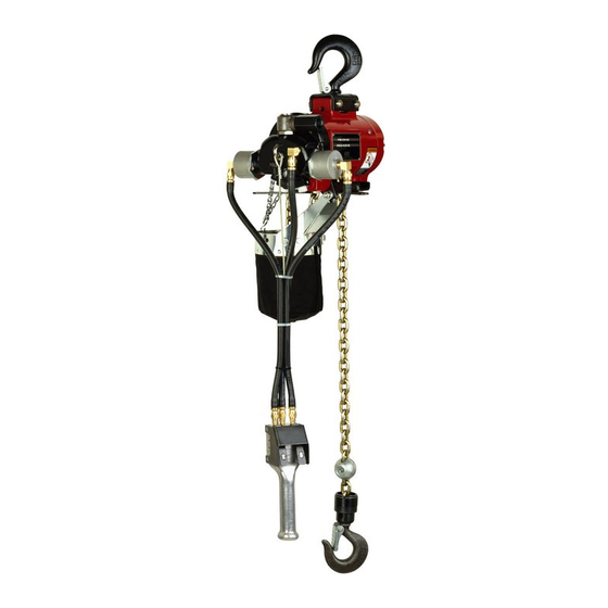
- Page 1 Chain Hoists Series 7700-E and 7700-ET Installation, Operation and Maintenance Save These Instructions Edition 5 November 2021 CCN 04615308...
- Page 2 Only allow Ingersoll Rand trained technicians to perform maintenance on this product. For additional information contact Ingersoll Rand factory or nearest Distributor. Manuals can be downloaded from ingersollrand.com The use of other than genuine Ingersoll Rand replacement parts may result in safety hazards, decreased performance and increased maintenance and will invalidate all warranties.
-
Page 3: Table Of Contents
Table of Contents Model Identification ................5 Installation . - Page 4 Table of Contents Pendant Control 3-Hose System ............. 29 Disassembly.
-
Page 5: Model Identification
Model Identification Model Code Explanation Example: 7770E-2C10-C6S 7770E Base Model: 7770E = 125 kg 1/8 T (275 lbs) 7718E 275 kg 1/4 T (550 lbs) 7756E 500 kg 1/2 T (1100 lbs) 7776E 1000 kg 1 T (2200 lbs) 7712EL 275 kg 1/4 T (550 lbs) Spark Resistant 7714EL... -
Page 6: Installation
Installation W W A A R R N N I I N N G G • THE HOISTING EQUIPMENT SHOWN AND DESCRIBED IN THIS MANUAL SHALL NOT BE USED TO LIFT OR TRANSPORT HUMAN CARGO. • The hoist shall be installed only in locations that will permit the operator to stand free of the load at all times. - Page 7 I I n n s s t t a a l l l l a a t t i i o o n n Figure 1. MHP3409 AIR INLET ADAPTER FOR MAIN AIR SUPPLY HOSE TO HOIST PENDANT CYLINDER ASSY (2) 45801 U-BRACKET 33989 STRAIN CABLE AIR SUPPLY HOSE TO...
-
Page 8: Air And Lube Requirements
Air and Lube Requirements Air Pressure of 90 psig (6 bar) at the air inlet of the hoist is required for maximum motor efficiency. If necessary, an air regulator should be installed to maintain this pressure when hoist is in operation. Filtered And Oiled Air will allow the hoist to operate more efficiently and yield a longer life to operating parts and mechanisms. -
Page 9: Operation
Operation W W A A R R N N I I N N G G • Do not operate this hoist before reading Product Information Manuals. • Read all documentation supplied with the product. • Contact factory if in doubt about installation, operation, inspection and maintenance instructions. - Page 10 O O p p e e r r a a t t i i o o n n Figure 2. MHP3410 REGULATOR VALVE Figure 3. MHP4608 RIGHT WRONG APPEARANCE OF CHAIN THAT APPEARANCE OF TWISTED HAS NOT BEEN TWISTED - CHAIN - ALTERNATING LINKS ALTERNATING LINKS FORM A DO NOT FORM A STRAIGHT...
-
Page 11: Inspection And Maintenance
Inspection and Maintenance ARO recognizes the need for periodic inspection of hoist components as an important step in preventive maintenance. The type of application for a hoist varies so greatly, it is impractical to recommend an exact time-table for inspection of the hoist, Where hoist is subjected to continuous operation with capacity loads, it is recommended the unit be inspected daily to weekly. -
Page 12: Brake
I I n n s s p p e e c c t t i i o o n n a a n n d d M M a a i i n n t t e e n n a a n n c c e e Brake 1. -
Page 13: Removal And Installation Of Load Chain
Removal and Installation of Load Chain LINK CHAIN HOISTS - A new chain should never be used on a worn pocketwheel. Replace chain and pocket-wheel as a pair. To remove chain; disconnect end of load chain from anchor lug on housing by removing screw (Y157-51) and washer (Y13-4-C). -
Page 14: Brake Adjustment
R R e e m m o o v v a a l l a a n n d d I I n n s s t t a a l l l l a a t t i i o o n n o o f f L L o o a a d d C C h h a a i i n n Figure 8. -
Page 15: Disassembly And Assembly
Disassembly and Assembly To minimize the possibility of ports damage and for convenience, the steps for disassembly or reassembly listed on the following pages are recommended. Removal of Hoist 1. Lower and disconnect load from hoist. 2. Shut off air at source and operate hoist control to bleed air from hoist and line. 3. - Page 16 D D i i s s a a s s s s e e m m b b l l y y a a n n d d A A s s s s e e m m b b l l y y Figure 10.
-
Page 17: Typical Cross Section
D D i i s s a a s s s s e e m m b b l l y y a a n n d d A A s s s s e e m m b b l l y y Typical Cross Section Figure 11. -
Page 18: Head Section
D D i i s s a a s s s s e e m m b b l l y y a a n n d d A A s s s s e e m m b b l l y y Head Section Figure 12. -
Page 19: Brake And Gearing Section
D D i i s s a a s s s s e e m m b b l l y y a a n n d d A A s s s s e e m m b b l l y y Brake and Gearing Section Figure 13. -
Page 20: Disassembly
D D i i s s a a s s s s e e m m b b l l y y a a n n d d A A s s s s e e m m b b l l y y Disassembly 1. -
Page 21: Housing Section
D D i i s s a a s s s s e e m m b b l l y y a a n n d d A A s s s s e e m m b b l l y y Housing Section Figure 15. -
Page 22: Disassembly
D D i i s s a a s s s s e e m m b b l l y y a a n n d d A A s s s s e e m m b b l l y y Disassembly 1. -
Page 23: Upper Hook Section
D D i i s s a a s s s s e e m m b b l l y y a a n n d d A A s s s s e e m m b b l l y y Upper Hook Section Figure 16. -
Page 24: Lower Hook Section
D D i i s s a a s s s s e e m m b b l l y y a a n n d d A A s s s s e e m m b b l l y y Lower Hook Section 400# &... -
Page 25: 1/4 And 1/2 Ton Link Chain Models
D D i i s s a a s s s s e e m m b b l l y y a a n n d d A A s s s s e e m m b b l l y y 1/4 and 1/2 Ton Link Chain Models Figure 18. -
Page 26: Ton Link Chain Models
D D i i s s a a s s s s e e m m b b l l y y a a n n d d A A s s s s e e m m b b l l y y 1 Ton Link Chain Models Figure 19. -
Page 27: 1600# Roller Chain Models
D D i i s s a a s s s s e e m m b b l l y y a a n n d d A A s s s s e e m m b b l l y y C C A A U U T T I I O O N N Make sure chain is not twisted and that welded side of links face away from sheave - see Installing Load Chain (MHP3428), p. - Page 28 D D i i s s a a s s s s e e m m b b l l y y a a n n d d A A s s s s e e m m b b l l y y Note: Assemble roll pin to hook with split side vertical with hook (either up or down).
-
Page 29: Controls Section
Controls Section Figure 21. 46094-6 Pendant Control Assembly (MHP3442) CYLINDER ASS'Y. (2) 45801 "O" RING Y325-13 CYLINDER 41064-1 PISTON 41066 ADAPTER 41067 "O" RING Y326-222 PISTON ROD 45799 "O" RING Y325-116 ELBOW Y54-23 SPRING 33981 ELBOW Y54-23 U-BRACKET (2) 33989 HOSE ASS'Y. -
Page 30: Assembly Of Controls To Hoist
C C o o n n t t r r o o l l s s S S e e c c t t i i o o n n Assembly of Controls to Hoist On pendant control models, control hoses must be attached to cylinder on head as follows: Facing air inlet of hoist, the hose to “DOWN”... - Page 31 C C o o n n t t r r o o l l s s S S e e c c t t i i o o n n 3-Hose System THE HOIST WILL ALWAYS CEASE OPERATION WHEN OPERATOR RELEASES THE PENDANT CONTROL. IF ANY HOSE (AIR INLET OR PENDANT CONTROL HOSES) SHOULD BECOME CUT OR RUPTURED - 1) RELEASE PENDANT CONTROL.
-
Page 32: Spark-Resistant Hoist Section
Spark-Resistant Hoist Section Load Chain Models Hook Max. Lift Rate Max. Descent Capacity (lbs) Hooks rate at 90 psig Mounting at 90 psig Type Number Zinc Plated, Link 50 fpm 70 fpm 7712EL 37708* Bronze Zinc Plated, Link 16 fpm 16 fpm 7714EL 1500... -
Page 33: Load Chain
S S p p a a r r k k - - R R e e s s i i s s t t a a n n t t H H o o i i s s t t S S e e c c t t i i o o n n Load Chain Zinc Plated Steel Link Chain 37708-( ) 550 lb. -
Page 34: Accessories Section
Accessories Section Piped Exhaust Exhaust from the air motor normally escapes into the room atmosphere, however, exhaust can be piped out of the room. The hoist can be furnished, at extra cost, with a modified head for piped exhaust. An exhaust hose, 1/2” (12 mm) diameter recommended, can then be attached to this outlet and air can be vented at any remote point. -
Page 35: Troubleshooting
Troubleshooting Hoist will not operate - check for: 1. Excessive Load. 2. Sufficient air pressure. 3. Clogged air intake screen. 4. Clogged valves. 5. Proper brake adjustment. 6. Proper installation of Roll Pin in Control Rod and Gear (34022). Unable to regulate hoist speed by controls check for: 1. -
Page 36: Service Kits
Service Kits Service Kit No. 41329–1 (For Link Chain Hoists) Qty. Description Qty. Description Part No. Part No. Bearing 33274 Lockwasher 33236 33387-2 Brake Shoe Kit 33330 Screw 34028 Filler Y117-616 Washer Safety Latch 35023 46072 Screen 41623 Gasket 31648 Screen O-Ring 41795... -
Page 37: Hose-Carrier Trolleys
S S e e r r v v i i c c e e K K i i t t s s Hose-Carrier Trolleys Figure 27. MHP3453 Model - 7703 Recommended when hoist is trolley-mounted. Adjustable clamp fits hose in sizes up to 1-1/4” o.d. can be mounted on the same beam that carries the hoist trolley. -
Page 38: Series 7700 Hoist Chain Basket Installation
Series 7700 Hoist Chain Basket Installation Figure 30. MHP3455 37602 37602 37602 37604 (2) 37602 Y100-624(2) Y5-55-0(2) BASKET LENGTH Y0-01-C(2) 37602 Y0-41-C (4) Y12-104-C(4) Y14-4C (4) Y14-4C (4) 45095030 TO BE INSTALLED IH 4TR LINK OF EACH 37653-( ) STRAND AND SCREWED CLOSED 37467-000-0 (7) (REF ,13 LINKS) - Page 39 N N o o t t e e s s...
- Page 40 ingersollrand.com ©2021 Ingersoll Rand...
Need help?
Do you have a question about the 7700-E Series and is the answer not in the manual?
Questions and answers