
Related Manuals for Ingersoll-Rand 7790-A Series


Summary of Contents for Ingersoll-Rand 7790-A Series
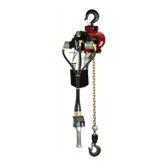
- Page 1 Air Hoist 7790-A and 7792-A Series Operator's Manual Save These Instructions Edition C February 2023 CCN 10590149...
- Page 2 Only allow Ingersoll Rand trained technicians to perform maintenance on this product. For additional information contact Ingersoll Rand factory or nearest Distributor. Manuals can be downloaded from ingersollrand.com The use of other than genuine Ingersoll Rand replacement parts may result in safety hazards, decreased performance and increased maintenance and will invalidate all warranties.
-
Page 3: Table Of Contents
Table of Contents Safety Information ................5 Operating Precautions . - Page 4 Table of Contents Motor Assembly................17 Trolley Assembly and Pull Chain Control Assembly .
-
Page 5: Safety Information
Safety Information Operating Precautions To aid the operator’s understanding of proper and safe use of hoists, the publication “Overhead Hoists”, ANSI B30.16-1981, can be purchased from: American Standards Institute, Inc. 1430 Broadway New York, New York 10018 • Do not use the hoist described in this manual to lift or transport humans. •... -
Page 6: Lubrication
Lubrication Routine Lubrication Requirements Lack of or an excessive amount of lubrication will affect the performance and life of this tool Use only recommended lubricants at below time intervals: Every 8 Hours Of Tool Operation — fill lubricator reservoir with spindle oil (29665). If an in line or air line lubricator is not used, fill oil reservoir of built-in oiler of hoist head. -
Page 7: Operation
Operation Suspending Hoist Adjusting Brake Always select an overhead support capable of supporting combined weight of hoist, trolley, and hoist’s load capacity. Hook Suspended Models • Upper hook should be firmly seated in center of hook saddle and that safety latch is closed. •... -
Page 8: Adjusting Brake
O O p p e e r r a a t t i i o o n n Adjusting Brake • Properly attach rated load of hoist to load chain hook. • Slowly raise load to 6” height above floor by slowly pulling pull chain handle or depressing pendent control. •... -
Page 9: Securing Load To Lift Chain
O O p p e e r r a a t t i i o o n n Securing Load to Lift Chain • Do Not Wrap Load Chain Around Load. Approved slings or other approved devices should be used to provide adequate single point securing of load to hoist load chain hook. -
Page 10: Routine Inspection
Routine Inspection The type of application for a hoist varies so greatly it is impractical to recommend an exact time-table for inspection of the hoist. Where hoist is subjected to continuous operation with capacity loads, it is recommended the unit be inspected twice a week. -
Page 11: Brake
R R o o u u t t i i n n e e I I n n s s p p e e c c t t i i o o n n Brake 1. Check brake operation - see “Adjusting Brake,”... -
Page 12: Maintenance
Maintenance Dissassembly Head Disassembly To remove head section from housing without disassembling head components, remove head with Control Rod (59) attached to Gear (25). To accomplish this: 1. Remove two Screws (96) and Housing Cap (95). 2. Drive out Roll Pin (61) and remove Brake Block (60). 3. -
Page 13: Pendent Control Disassembly
M M a a i i n n t t e e n n a a n n c c e e Pendent Control Disassembly 1. Remove pendent hoses from Fittings (156) and (165). 2. Remove Adapter (166) from head releasing strain cable. 3. -
Page 14: Upper Hook Disassembly
M M a a i i n n t t e e n n a a n n c c e e Upper Hook Disassembly 1. Remove Nuts (153), Washers (152) and Bracket (150). 2. Drive out Roll Pin (147) - One-Ton Models. Roll pins (155) and (154) - Two-Ton Models. 3. -
Page 15: Assembly
Assembly Brake and Gearing Assembly 1. Lubricate and assemble six O-Rings (86) into counterbores of fixed Ring Gear (84). 2. Assemble Seal (88) to End Plate (89) - lip of seal facing out. 3. Assemble wave Washer (87) and End Plate (89) to fixed Ring Gear (84) and secure with four Washers (102) and shoulder Screws (101). -
Page 16: Upper Hook Assembly
A A s s s s e e m m b b l l y y 6. Assemble Plate (65), Washers (66) and Screws (67) to housing. 7. Assemble New Seal (52) into housing with lip of seal facing out. 8. -
Page 17: Motor Assembly
A A s s s s e e m m b b l l y y Motor Assembly 1. Lubricate Bearings (37) with NLGI #1 “EP” grease (33153) and assemble bearings to End Plate (38) and (43) - shielded side of bearing facing out. 2. -
Page 18: Trolley Assembly And Pull Chain Control Assembly
Trolley Assembly and Pull Chain Control Assembly Figure 11. Trolley Assembly Drawing (MHP4730) CAUTION: TIGHTEN NUTS 25 TO 30 FT. LB TORQUE ONLY. Figure 12. Pull Chain Control Assembly Drawing (MHP4736) DOWN... -
Page 19: Brake And Gearing Section Drawing
Brake and Gearing Section Drawing Figure 13. (MHP4731) -
Page 20: Upper Hook And Lower Hook Assembly
Upper Hook and Lower Hook Assembly Figure 14. Upper Hook Assembly Drawing (MHP4733) ( 2-TON MODELS) 123 ( 1-TON MODELS) 149 122 ( 2-TON MODELS) 148 ( 1-TON MODELS) CAUTION : TIGHTEN NUTS 25 TO 30 FT. LBS. TORQUE ONLY. (1-TON MODELS) ++ ASSEMBLE WITH SPLIT SIDE ONE UP AND ONE DOWN. -
Page 21: Housing Assembly Drawing
Housing Assembly Drawing Figure 16. (MHP4737) PART NUMBERTHIS SIDE. -
Page 22: Pendant Control Assembly Drawing
Pendant Control Assembly Drawing Figure 17. (MHP4734) ITEMS INCLUDED IN SERVICE KIT PART NUMBER 41619-1. ITEMS INCLUDED IN SERVICE KIT PART NUMBER 41759. ITEMS INCLUDED IN 43004 SHAFT ASSEMBLY... -
Page 23: 7790-A And 7792-A Series Parts List
7790-A and 7792-A Series Parts List Description of Part Item No. Part Number Head Assembly (standard models) includes items 1 thru 21, 24 thru 30, 33 and 34 46126-2 with adapter (46211) Head Assembly (spark-resistant models) (includes items 1 thru 19, 24 thru 30, 33, 46126-3 34 and 59 with adapter 46212) Adapter... - Page 24 7 7 7 7 9 9 0 0 - - A A a a n n d d 7 7 7 7 9 9 2 2 - - A A S S e e r r i i e e s s P P a a r r t t s s L L i i s s t t Description of Part Item No.
- Page 25 7 7 7 7 9 9 0 0 - - A A a a n n d d 7 7 7 7 9 9 2 2 - - A A S S e e r r i i e e s s P P a a r r t t s s L L i i s s t t Description of Part Item No.
- Page 26 7 7 7 7 9 9 0 0 - - A A a a n n d d 7 7 7 7 9 9 2 2 - - A A S S e e r r i i e e s s P P a a r r t t s s L L i i s s t t Description of Part Item No.
- Page 27 7 7 7 7 9 9 0 0 - - A A a a n n d d 7 7 7 7 9 9 2 2 - - A A S S e e r r i i e e s s P P a a r r t t s s L L i i s s t t Description of Part Item No.
- Page 28 7 7 7 7 9 9 0 0 - - A A a a n n d d 7 7 7 7 9 9 2 2 - - A A S S e e r r i i e e s s P P a a r r t t s s L L i i s s t t Description of Part Item No.
-
Page 29: Parts List For Model Identification And Spark Resistant
Parts List for Model Identification and Spark Resistant Table 2. Model Identification Upper Mounting Type Control Type Load Chain Lb. (Kg.) Capacity Model No. Hook Assembly 43002 7790-A9 Pull Chain Link None 7790-A11 Pull Chain Link 2,200 (1000 Kg) Hook Assembly 43002 7790-A13 Pendent Link... - Page 30 N N o o t t e e s s...
- Page 31 N N o o t t e e s s...
- Page 32 i i n n g g e e r r s s o o l l l l r r a a n n d d .c c o o m m ©2023 Ingersoll Rand...
Need help?
Do you have a question about the 7790-A Series and is the answer not in the manual?
Questions and answers