
Related Manuals for Ingersoll-Rand Hercu-Link BHS Series


Summary of Contents for Ingersoll-Rand Hercu-Link BHS Series
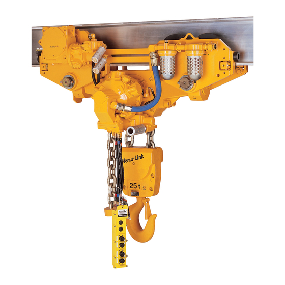
- Page 1 Hercu-Link™ Air B.O.P. Handling Systems Models BHS 50 (50 Metric Tons) BHS 75 (75 Metric Tons) BHS 100 (100 Metric Tons) BHS 150 (150 Metric Tons) Product Information Save These Instructions Edition A May 2018 CCN 47638924...
- Page 2 Only allow Ingersoll Rand trained technicians to The use of other than genuine Ingersoll Rand perform maintenance on this product. For additional replacement parts may result in safety hazards, information contact Ingersoll Rand factory or nearest decreased performance and increased maintenance Distributor.
-
Page 3: Table Of Contents
Table of Contents Product Description ......4 Hoist Controls ......10 Accu-Trol®... -
Page 4: Product Description
Output from planetary downward load drift. reduction section is transmitted directly to load chain Contact your Ingersoll Rand authorized service sheave(s). provider for any parts/service/ inspection/support The motor-driven brake shaft is connected to brake related needs. - Page 5 P P r r o o d d u u c c t t D D e e s s c c r r i i p p t t i i o o n n...
-
Page 6: Specifications
Specifications Table 2. General Specifications Air Consumption @ Chain Rated Load Chain Standard Lift Rated Load Size Hoist Model Capacity Falls / metric tons Each Hoist m³/min scfm BHS50 BHS75 BHS100 BHS150 Speed at 105 psi Speed at 60 psi (700 kPa / 7 bar) (400 kPa / 4 bar) Hoist Model... -
Page 7: Installation
Installation Prior to installing the product, carefully inspect it for valves, etc. cause a reduction in pressure due to possible shipping damage. Products are supplied fully restrictions and surface friction in lines. lubricated from the factory. Check oil levels and adjust Air Line Lubricator as necessary before operating product. -
Page 8: Hoist And Trolley Motors
I I n n s s t t a a l l l l a a t t i i o o n n Hoist and Trolley Motors into place on beam flange. For optimum performance and maximum durability of C C A A U U T T I I O O N N parts, provide an air supply to operate hoist and trolley motors with 105 psi at 280 scfm (700 kPa/7 bar at 8 cu. -
Page 9: Installing Rack Segments Onto
I I n n s s t t a a l l l l a a t t i i o o n n Attaching Limit Stop Adjust Clearance Refer to Figure 9, p. 1. Install limit stop as described under ‘Load Chain Replacement‘. -
Page 10: Operation
Operation The four most important aspects of hoist operation are: responsibility to refuse to operate hoist under unsafe conditions. 1. Follow all safety instructions when operating hoist and trolley. Hoist Controls 2. Allow only people trained in safety and operation of this product to operate hoist and trolley. -
Page 11: Inspection
6. Controls: During operation of the hoist, verify that operators or Ingersoll Rand trained inspectors and response to pendant is quick and smooth. Ensure include observations made during routine equipment controls return to neutral when released. -
Page 12: Load Chain Reports
“Frequent Inspection,” p. 11 inspected further by an Ingersoll Rand trained inspector. Refer to Product Maintenance section before being placed in service. Information Manual. -
Page 13: Lubrication
Approval for use of other lubricants must be obtained important to use only high quality, rust and oxidation- from your Ingersoll Rand distributor. Failure to observe inhibiting lubricant to insure maximum performance this precaution may result in damage to hoist and/ or and minimum down time for repairs. -
Page 14: Trolley Drive Assembly
L L u u b b r r i i c c a a t t i i o o n n Trolley Drive Assembly maintained at correct level. Oil capacity for reduction gear assembly is 1.1 gals (4.2 ltr). Refer to MHP0306 in the Product Parts Information Manual. -
Page 15: Product Information Graphics
Product Information Graphics Figure 1. MHP4244 Brake Hoist Motor Trolley Motor Spring Release (down only) Brake Exhaust Limit Paddle 1" 1" Lubricator Air Supply Filter/ Separator Off On Accu-Trol Hoist Hoist Down Trolley Trolley Left Right... - Page 16 P P r r o o d d u u c c t t I I n n f f o o r r m m a a t t i i o o n n G G r r a a p p h h i i c c s s Figure 2.
- Page 17 P P r r o o d d u u c c t t I I n n f f o o r r m m a a t t i i o o n n G G r r a a p p h h i i c c s s Figure 5.
- Page 18 P P r r o o d d u u c c t t I I n n f f o o r r m m a a t t i i o o n n G G r r a a p p h h i i c c s s Figure 10.
-
Page 19: Maintenance Intervals
Disc Brake Grease Fittings Lubricate grease fittings every 90 days. Lubricate chain every 7 days. Chain The following work shall be completed by an Ingersoll Rand trained service technician or a Qualified Person. Components 1 year 2 years 3 years... - Page 20 Ingersoll Rand has a policy of continuous product and product data improvements and reserves the right to change design and specifications without notice. We are committed to using environmentally conscious print practices.
Need help?
Do you have a question about the Hercu-Link BHS Series and is the answer not in the manual?
Questions and answers