Table of Contents

Subscribe to Our Youtube Channel
Related Manuals for Ingersoll-Rand 7700-E Series


Summary of Contents for Ingersoll-Rand 7700-E Series
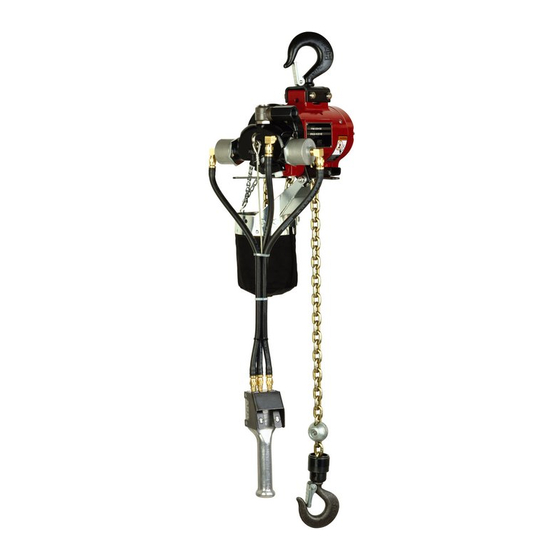
- Page 1 Form 04615308 Edition 2 September 2005 CHAIN HOISTS Series 7700-E & 7700-ET Distributed by Tri-State Equipment Company Inc. Email: sales@tsoverheadcrane.com Web: www.tsoverheadcrane.com PH: 314-869-7200 | FAX: 314-869-7226 Operator’s Manual Save These Instructions...
-
Page 2: Model Identification
MODEL IDENTIFICATION MODEL NUMBER UPPER MOUNTING TYPE CONTROL TYPE LOAD CHAIN 400# 800# 1600# 7719-E 7700-E 7725-E 34921 HOOK ASSEMBLY PULL CHAIN ROLLER 7719-ET 7700-ET 7725-ET TROLLEY ADAPTER PULL CHAIN ROLLER 7720-E 7708-E 7732-E 34921 HOOK ASSEMBLY PENDENT ROLLER 7720-ET 7708-ET 7732-ET TROLLEY ADAPTER... - Page 3 trolley adapter at each side and assemble these spacers to Connect hoist to nearest air source using a minimum 1/2” i.d. the outside of the side plates between the side plate and lock air hose assembly. Sufficient air hose must be provided to nuts.
-
Page 4: Operation
AIR AND LUBE REQUIREMENTS AIR PRESSURE of 90 p.s.i.g. (6 bar) at the air inlet of the chain should be cleaned and relubricated with greater hoist is required for maximum motor efficiency. If necessary, frequency to remove grit, sand and other contaminants. an air regulator should be installed to maintain this pressure OIL RESERVOIR in head should be filled with spindle oil when hoist is in operation. - Page 5 CAUTION WARNING DO NOT OPERATE HOIST WITHOUT CHAIN STOP MAXIMUM LOWERING SPEED WITH RATED CAPACITY ATTACHED PROPERLY TO HOIST LOAD CHAIN. DO NOT LOAD IS VERY HIGH. ADJUST WITH CARE. USE CHAIN STOP AS A LIMIT SWITCH (to stop hoist when operating in the “up”...
-
Page 6: General Maintenance
LOAD CHAIN AND ANCHORS CORRECT HOOK OPENING a. Visually check for nicked, gouged, twisted, bent, corroded, rusted, worn or broken links. Check ends of chain where chain is anchored to hoist frame and where 1-1/8" (29 mm) ON 1/4 & 1/2 TON MODELS (LOWER HOOKS). -
Page 7: Brake Adjustment
REMOVAL AND INSTALLATION OF LOAD CHAIN REMOVAL LINK CHAIN HOISTS - A new chain should never be used on WARNING a worn pocketwheel. Replace chain and pocket-wheel as a pair. To remove chain; disconnect end of load chain from anchor lug on housing by removing screw (Y157-51) and DO NOT attempt to feed chain over pocketwheel or washer (Y13-4-C). - Page 8 DISASSEMBLY AND REASSEMBLY To minimize the possibility of ports damage and for convenience, the steps for disassembly or reassembly listed on the following pages are recommended. "TIMING OF HEAD" REMOVAL OF HOIST STEP-1 a. Lower and disconnect load from hoist. ENDS OF VALVE BODY FLUSH WITH BUSHING.
- Page 9 TYPICAL CROSS SECTION - ET 400 LB. & 1/4 TON 800 & 1600 LB. 1/2 & 1 TON 800 LB. & 1/2 TON LINK CHAIN ROLLER CHAIN 400 & 800 LB. 1/4 & 1/2 TON LOWER BLOCK LOWER BLOCK LINK CHAIN ROLLER CHAIN 1600 LB.
- Page 10 HEAD SECTION DISASSEMBLY REASSEMBLY a. Remove head from housing as outlined on page 8. a. Assemble screen (33672) and fillers (34028) to head. b. Remove lock screw (34024), gear (34030) and shaft Assuming other hoist components are assembled to (34025). housing, assemble head to housing with gasket (41623).
- Page 11 c. On 1/2 and 1 ton models, assemble wear plates (45909), Assemble steel balls (Y 16-10) and screw (37701) into gear assemblies and bushings to end plate and secure bracket. Position brake shoes (33387 or 33387-1) over with support ring, screws (Y194-44), bolts (33369), brake wheel and assemble brake spring (33281) over washers (Y1-516) and nuts (33368).
-
Page 12: Motor Section
MOTOR SECTION CYLINDER 34032 (STANDARD DESCENT) 33235 BEARING (PAIRED) Y200-59 SCREW TORQUE TO 90-110 IN. LBS. 33277 KEY 46074 END PLATE 33373 SPINDLE 43068 ROTOR Y325 154 ‘‘O” RING 33284 END PLAT E Y325-12 "O" RING (2) 33272 SPACER (2) 33274 WASHER 34541 CYLINDER (EXTRA - FAST DESCENT) - Page 13 g. Assemble hangers (37585) and control arm (37719) to h. On 1 ton models, assemble anchor bracket (37579) to housing hangers (37585) and secure with washers (37587) and anchor bolts (37586). (NOTE: Assemble control arm in housing with arms for For installation of load chain, see page 7.
- Page 14 UPPER HOOK SECTION DISASSEMBLY a. To remove upper hook assembly from housing, remove nuts (Y109-624) and bolts (41599). b. To disassemble hook assembly, drive out roll pin HOOK (SEE TABLE) (Yl78-122) from collar (34321). SAFETY LATCH 35023 HOOK ASSY. c. Removing collar will release steel balls and bracket from (SEE TABLE) * NOT INCLUDED WITH hook and latch assembly.
- Page 15 LOWER HOOK SECTION 1/4 AND 1/2 TON LINK CHAIN MODELS SCREW Y157-51 WASHER Y13-4-C LINK CHAIN 37708-11 SEE PAGES 20 & 21 FOR SPARK-RESISTANT LOAD CHAIN SCREW Y19-113-C CHAIN STOP (2) 34994 STOP NUT Y109-324 CHAIN STOP ASSEMBLY 34981 SNAP RING 35016 SLEEVE 35017 CONNECTOR 34989 ASSEMBLE ROLL PINS WITH SLOTS...
- Page 16 1 TON LINK CHAIN MODELS LINK CHAIN 37708-22 SEE PAGES 20 & 21 FOR SPARK- RESISTANT LOAD CHAIN. CHAIN WASHER Y13-4-C STOP 37666 SCREW Y157-51 SHEEVE 45364 NUT (3) Y107-4-Z BEARING (2) 42406 SHROUD (2) 45362-1 SCREW Y99-43 1 TON CAUTION DO NOT TWIST...
- Page 17 1600# ROLLER CHAIN MODELS CONNECTING LINK 33363 ROLLER CHAIN 34331-11 ROLLER CHAIN 34332-22 ASS'Y. ANCHOR BLOCK 44686 SEE PAGES 20 & 21 FOR SPARK- RESISTANT LOAD CHAIN. CHAIN STOP 37666 SCREW Y157-51 SHEEVE 45364 NUT (3) Y107-4-Z BEARING (2) 42406 SHROUD (2) 45363-1 SCREW Y99-43 CAUTION...
-
Page 18: Controls Section
CONTROLS SECTION CYLINDER ASS'Y. (2) 45801 "O" RING Y325-13 CYLINDER 41064-1 PISTON 41066 ADAPTER 41067 "O" RING Y326-222 PISTON ROD 45799 "O" RING Y325-118 ELBOW Y54-23 SPRING 33981 ELBOW Y54-23 U-BRACKET (2) 33989 HOSE ASS'Y. 43103-6 HANDLE ASS'Y. 43102 CONNECTOR (3) Y54-2 "O"... - Page 19 "S" HOOK (2) 37659 INCLUDED WITH 44806 CONTROL HANDLE HANDLE (2) 33268 LABEL 44596 CHAIN (2) 37657-5 CONTROL HANDLE 44806 ANCHOR (2) 37723 40004-5 PULL CHAIN CONTROL ASSEMBLY FIGURE 19 On pull chain control models, control chains must be installed ‘‘B”...
- Page 20 SPARK-RESISTANT HOIST SECTION MODELS LOAD CHAIN MAX. LIFT MAX. DESCENT CAPAClTY Hook HOOKS CONTROLS RATE AT RATE AT 90 (lbs) TYPE NUMBER LIFT Mounting 90 P.S.I. P.S.I. 7712-E Stainless, Roller 34043-11 10’ (3.0 m) Bronze Pull Chain 40 F.P.M. 40 F.P.M. 7712-EL Stainless, Link 39489-11 10’...
-
Page 21: Load Chain
LOAD CHAIN STAINLESS STEEL LINK CHAIN 39489-( ) 34042 (2) CONN. LINK FOR 250 kg (550 lb.) AND 1500 lb. CAPACITY HOIST Dash number indicates exact length in feet. For 550 lb. capacity hoists, order lift footage and add one extra foot for 34041-( ) CHAIN assembly. -
Page 22: Accessories Section
ACCESSORIES SECTION TYPE BEAM FLANGE MINIMUM MODEL NO. CAP. (LBS.) BEAM SIZE WIDTH TURNING RADIUS 7702 1/2 - TON L-BEAM 4" TO 10" 2.660" TO 4.660" 24 INCHES 7761-BC * 1/2 - TON L-BEAM 4" TO 10" 2.660" TO 4.660" 24 INCHES 1/2 - TON H-BEAM... -
Page 23: Service Kits
TROUBLE SHOOTING HOIST WILL NOT OPERATE - CHECK FOR: HOIST LOSES POWER - CHECK FOR: 1. Excessive Load 1. Sufficient air pressure. 2. Sufficient air pressure. 2. Clogged air intake screen. 3. Clogged air intake screen. 3. Clogged muffler screen or filler. 4. - Page 24 BULLARD SNAP HOOKS 43232 CLAMP (2) 35205-1 Lower Hook Assembly for 1/4 and 1/2 Ton ROLLER CHAIN only. Includes Bucket Swivel, 43230 RESTRAINING CABLE Steel Balls, Collar, Roll Pins, Connector and Pin. (1/4" DIA x 2 FT. LONG) 35206 Lower Hook Assembly for 1/4 and 1/2 Ton LINK CHAIN only.
- Page 25 SERIES 7700 HOIST CHAIN BASKET INSTALLATION BOLT (2) Y6-61-C BRACKET 34706 "S" HOOK (4) 37659 SASH CHAIN (2)-37657-000-G NOTE: ATTACH "S" HOOK TO FOURTH LINK FROM TOP AND CLOSE ENDS. NUT (2) Y109-524 * WASHER (2) Y14-516 * SPACER (2) 37594 * WASHER (2) 37587 * BOLT (2) 37586 ANCHOR BRACKET 41624 *...
- Page 26 NOTES Form 04615308-Edition 2...
- Page 27 NOTES Form 04615308-Edition 2...
- Page 28 Distributed by Tri-State Equipment Company Inc. Email: sales@tsoverheadcrane.com www.irtools.com Web: www.tsoverheadcrane.com PH: 314-869-7200 | FAX: 314-869-7226 Ingersoll-Rand © 2005 Company...
Need help?
Do you have a question about the 7700-E Series and is the answer not in the manual?
Questions and answers