Table of Contents
Advertisement
Quick Links
UM11712
PCAL6534EV-ARD evaluation board
Rev. 1.0 — 31 January 2022
Document information
Information
Content
Keywords
PCAL6534, I
Abstract
The PCAL6534EV-ARD evaluation board is a daughter card equipped with
an Arduino port, designated for easy test and design of PCAL6534 IC, 34-bit
port expander, controlled through FM+ I
is fully compliant with IMXRT1050 EVK, LPCXpresso55S69 (LPC55S69-
EVK) and i.MX 8M Mini LPDDR4 EVK (8MMINILPD4-EVK, 8MMINID4-EVK),
including GUI software control. The board can be attached to any device
equipped with an Arduino port.
2
C-bus, 34-bit I/O bus, Arduino port, EVK
User manual
2
C 2-wire bus, with RESET. The board
Advertisement
Table of Contents

Related Manuals for NXP Semiconductors UM11712


Summary of Contents for NXP Semiconductors UM11712
- Page 1 UM11712 PCAL6534EV-ARD evaluation board Rev. 1.0 — 31 January 2022 User manual Document information Information Content Keywords PCAL6534, I C-bus, 34-bit I/O bus, Arduino port, EVK Abstract The PCAL6534EV-ARD evaluation board is a daughter card equipped with an Arduino port, designated for easy test and design of PCAL6534 IC, 34-bit port expander, controlled through FM+ I C 2-wire bus, with RESET.
- Page 2 UM11712 NXP Semiconductors PCAL6534EV-ARD evaluation board Revision history Date Description v.1.0 20220131 Initial version UM11712 All information provided in this document is subject to legal disclaimers. © NXP B.V. 2022. All rights reserved. User manual Rev. 1.0 — 31 January 2022...
- Page 3 UM11712 NXP Semiconductors PCAL6534EV-ARD evaluation board IMPORTANT NOTICE For engineering development or evaluation purposes only NXP provides the product under the following conditions: This evaluation kit is for use of ENGINEERING DEVELOPMENT OR EVALUATION PURPOSES ONLY. It is provided as a sample IC pre- soldered to a printed-circuit board to make it easier to access inputs, outputs and supply terminals.
-
Page 4: Introduction
IMXRT1050 EVK Board, LPCXpresso55S69 Development Board and i.MX 8M Mini LPDDR4 EVK Board. Finding kit resources and information on the NXP web site NXP Semiconductors provides online resources for evaluation board and its supported device(s) on http://www.nxp.com. The information page for PCAL6534EV-ARD evaluation board is at http://http:// www.nxp.com/PCAL6534EV-ARD. -
Page 5: Assumptions
UM11712 NXP Semiconductors PCAL6534EV-ARD evaluation board • Quick Start Guide 3.2 Assumptions Familiarity with the I C-bus is helpful but not required. 3.3 Static handling requirements CAUTION This device is sensitive to ElectroStatic Discharge (ESD). Therefore care should be taken during transport and handling. You must use a ground strap or touch the PC case or other grounded source before unpacking or handling the hardware. -
Page 6: Block Diagram
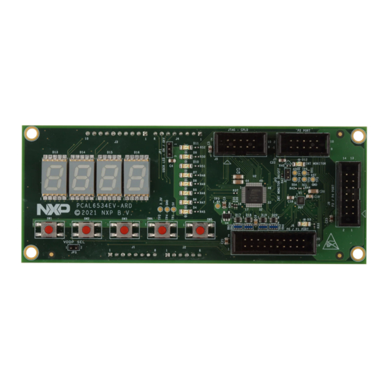
UM11712 NXP Semiconductors PCAL6534EV-ARD evaluation board Figure 1. The PCAL6534EV-ARD board picture, top view (up) and bottom view (down) 4.3 Block diagram Figure 2 shows a block diagram of the PCAL6534EV-ARD daughter board. Alongside the DUT (U1), the board includes a series of peripherals that assures the operation of the board. -
Page 7: Schematic Diagram
UM11712 NXP Semiconductors PCAL6534EV-ARD evaluation board D13 - D16 MAX V CPLD INTEL PCAL6534 34 BIT I/O EXPANDER ARDUINO INTERFACE P0_0 to P0_7 16 BIT I/O PORT P1_0 to P1_7 USER LEDs CONTROL BUS P2_0 to P2_7 8 BIT I/O PORT 3.3V... -
Page 8: I2C-Bus
UM11712 NXP Semiconductors PCAL6534EV-ARD evaluation board Table 1. The pin chart of Arduino connectors and their usage ...continued Ref Des Arduino label PCAL6534EV-ARD function Not used Not used A4 / SDA C – SDA A5 / SCL C – SCL D0 / RX... -
Page 9: Control Bus
UM11712 NXP Semiconductors PCAL6534EV-ARD evaluation board 4.7 Control bus The control bus manages RESET, ADDR, and INT pins of the PCAL6534 IC. The RESET pin is digital input and is controlled by the system host. Its role is to reset the I/ O expander when a time-out or other improper operation occurs. -
Page 10: Cpld
UM11712 NXP Semiconductors PCAL6534EV-ARD evaluation board Table 2. The I/O allocation table ...continued PCAL6534 CPLD 16 BIT – I/ 8 BIT – I/O 10 BIT – I/ Direction Switch (U1) pin (U2) pin O PORT (J6) PORT (J7) O PORT (J9) -
Page 11: Direct Write
UM11712 NXP Semiconductors PCAL6534EV-ARD evaluation board Table 3. CPLD control bus Bus line Direct Write Count Idle MAX_CLK Not used Not used Not used MAX_CLR MAX_OE Controls the speed MAX_CTRL_0 of counting Controls the indication Controls the direction MAX_CTRL_1 of digit 4 (D9) -
Page 12: Count Mode
UM11712 NXP Semiconductors PCAL6534EV-ARD evaluation board 4.9.2 Count mode In this mode, an internal counter clocked by the RC oscillator of MAX V counts up and down, at low speed (clock frequency: 7.6 Hz), or high speed (clock frequency: 61 Hz). -
Page 13: Jumpers And Test Points
UM11712 NXP Semiconductors PCAL6534EV-ARD evaluation board Count mode - counting up Count mode - counting down Idle mode Figure 3. PCAL6534EV-ARD on-board LED display 4.10 Jumpers and test points The board contains two jumpers and several test points. Table 6 Figure 4 details the jumper locations and their default configurations. -
Page 14: Installing And Configuring Software Tools
UM11712 NXP Semiconductors PCAL6534EV-ARD evaluation board Table 6. PCAL6534EV-ARD jumpers ...continued Ref Des Label Default Description ON: Enable the interrupt monitor LED (D12) Figure 4. PCAL6534EV-ARD Jumper locations Table 7. PCAL6534EV-ARD test points Ref Des Test point / jumper label Description 5 V power supply 3.3V... -
Page 15: Configuring The Hardware
UM11712 NXP Semiconductors PCAL6534EV-ARD evaluation board Additionally, a GUI application (Windows 10) is available for download from the NXP site, allowing rapid testing and operation of PCAL6534EV-ARD daughterboard through one of above mentioned EVKs. The GUI application is common for all three EVKs and for the PCAL6xxx I/O expander development card family, manufactured by NXP (PCAL6408A, PCAL6416A, PCAL6524 and PCAL6534 ICs). - Page 16 UM11712 NXP Semiconductors PCAL6534EV-ARD evaluation board Figure 5. PCAL6534EV-ARD daughterboard and IMXRT1050 EVK board, before starting To configure the hardware and workstation, complete the following procedure: 1. Configure the suitable power configuration of EVK (J1). If using J28 for power supply, the J1 jumper shall be placed in position 5-6.
-
Page 17: Lpcxpresso55S69 Development Board
UM11712 NXP Semiconductors PCAL6534EV-ARD evaluation board 6.2 Using the PCAL6534EV-ARD with an LPCXpresso55S69 development board Figure 7 shows the required hardware for operation of the PCAL6534EV-ARD and LPCXpresso55S69 EVK board. This configuration consists of: • One LPCXpresso55S69 EVK board • One PCAL6534EV-ARD daughterboard •... - Page 18 UM11712 NXP Semiconductors PCAL6534EV-ARD evaluation board Figure 7. PCAL6534EV-ARD daughterboard and LPCXpresso55S69 motherboard, before starting The following steps describe how to assemble, program, and operate the configuration shown in Figure UM11712 All information provided in this document is subject to legal disclaimers.
-
Page 19: Using The Pcal6534Ev-Ard With An I.mx
UM11712 NXP Semiconductors PCAL6534EV-ARD evaluation board 1. Insert the PCAL6534EV-ARD daughter card to P16 – P19 connectors located on LPCXpresso55S69 development board (see the marked pins of P16 – P19, Figure 2. Connect the development board using port P6 USB port of PC;... - Page 20 UM11712 NXP Semiconductors PCAL6534EV-ARD evaluation board To operate the setup, along with the EVK and the daughterboard, a third board must be included in the setup assembly. Figure 9 shows the necessary boards and how these boards are connected. The configuration consists of: •...
-
Page 21: Using Pcal6534Ev-Ard With Another Device
IC damage. GUI description A GUI application is available for the three EVK boards from NXP Semiconductors. The application is common for all EVKs and the development boards of the entire family of IO UM11712 All information provided in this document is subject to legal disclaimers. - Page 22 UM11712 NXP Semiconductors PCAL6534EV-ARD evaluation board expanders produced by NXP Semiconductors (PCAL6408A-ARD, PCAL6416AEV-ARD, PCAL6524EV-ARD, and PCAL6534EV-ARD). This section describes the GUI application and how the user can control the PCAL6534EV-ARD daughterboard from the graphical interface. First, install the GUI package and software on the PC (Windows 10). For more details, see UM11581.
- Page 23 UM11712 NXP Semiconductors PCAL6534EV-ARD evaluation board In the tab bar, from left to right the first tab is CPLD. Clicking on CPLD tab, a new window appears as it is shown in Figure 12. The user can select one of three modes: •...
- Page 24 UM11712 NXP Semiconductors PCAL6534EV-ARD evaluation board select and activate the internal pull-up resistors from the GUI. In the right side of the window, the Read button, bring back the current values of the registers on the graphical user interface. Figure 13. Graphical interface – “SWITCH” tab activated The LED tab, allows the user to control the on-board user LEDs D4 to D11.
- Page 25 UM11712 NXP Semiconductors PCAL6534EV-ARD evaluation board Figure 14. Graphical interface – “LED” tab activated The GPIO tab (Figure 15) is managing the remaining I/O lines of the DUT IC, which are not allocated to the on-board peripheral (LED, switch, or on-board display). The lines are the first five LSB of port P3, and are linked to connector J8 (see section 5.8 “I/O bus”).
- Page 26 UM11712 NXP Semiconductors PCAL6534EV-ARD evaluation board Figure 15. Graphical interface – “GPIO” tab activated The Debug tab (Figure 16) displays the current value of the internal registers of the IC, every time when Read button is clicked. To find details about internal registry see the PCAL6534 datasheet.
-
Page 27: Abbreviations
UM11712 NXP Semiconductors PCAL6534EV-ARD evaluation board Figure 16. Graphical interface – “Debug” tab activated Abbreviations Table 8. Abbreviations Acronym Description CPLD Complex Programmable Logic Device Device Under Test Electro Static Discharge Evaluation Board Graphical User Interface C-bus Inter-Integrated Circuit bus Integrated Circuit... -
Page 28: References
1. PCAL6534, Ultra low-voltage translating 34-bit FM+ I C-bus/SMBus I/O expander with Agile I/O features, interrupt output and reset Product data sheet; NXP Semiconductors; 2. MIMxrt1050 EVK Board Hardware User’s Guide User manual; NXP Semiconductors; 3. i.MX RT1050 Crossover Processors Data Sheet for Consumer Products Data sheet;... -
Page 29: Legal Information
NXP Semiconductors. whatsoever (including without limitation, all damages referenced above and In no event shall NXP Semiconductors be liable for any indirect, incidental, all direct or general damages), the entire liability of NXP Semiconductors, punitive, special or consequential damages (including - without limitation - its affiliates and their suppliers and customer’s exclusive remedy for all of... - Page 30 UM11712 NXP Semiconductors PCAL6534EV-ARD evaluation board Tables Tab. 1. The pin chart of Arduino connectors and Tab. 5. MAX_CTRL_# control lines ......12 their usage ............7 Tab. 6. PCAL6534EV-ARD jumpers ......13 Tab. 2. The I/O allocation table ........9 Tab.
-
Page 31: Table Of Contents
'Legal information'. © NXP B.V. 2022. All rights reserved. For more information, please visit: http://www.nxp.com For sales office addresses, please send an email to: salesaddresses@nxp.com Date of release: 31 January 2022 Document identifier: UM11712...
Need help?
Do you have a question about the UM11712 and is the answer not in the manual?
Questions and answers