Table of Contents
Advertisement
Quick Links
UM11729
FRDMGD3162HBIEVM half-bridge evaluation board
Rev. 1 — 21 February 2022
Document information
Information
Content
Keywords
automotive, half-bridge, GD3162, gate driver
Abstract
This document describes key features and usage requirements for performing
evaluation of GD3162 gate driver with FRDMGD3162HBIEVM.
User manual
Advertisement
Table of Contents

Subscribe to Our Youtube Channel
Related Manuals for NXP Semiconductors SAFE ASSURE UM11729


Summary of Contents for NXP Semiconductors SAFE ASSURE UM11729
- Page 1 UM11729 FRDMGD3162HBIEVM half-bridge evaluation board Rev. 1 — 21 February 2022 User manual Document information Information Content Keywords automotive, half-bridge, GD3162, gate driver Abstract This document describes key features and usage requirements for performing evaluation of GD3162 gate driver with FRDMGD3162HBIEVM.
- Page 2 UM11729 NXP Semiconductors FRDMGD3162HBIEVM half-bridge evaluation board Revision history Date Description 20220221 initial version UM11729 All information provided in this document is subject to legal disclaimers. © NXP B.V. 2022. All rights reserved. User manual Rev. 1 — 21 February 2022...
-
Page 3: Important Notice
UM11729 NXP Semiconductors FRDMGD3162HBIEVM half-bridge evaluation board Important notice IMPORTANT NOTICE For engineering development or evaluation purposes only NXP provides the product under the following conditions: This evaluation kit is for use of ENGINEERING DEVELOPMENT OR EVALUATION PURPOSES ONLY. It is provided as a sample IC pre-soldered to a printed-circuit board to make it easier to access inputs, outputs and supply terminals. -
Page 4: Getting Started
UM11729 NXP Semiconductors FRDMGD3162HBIEVM half-bridge evaluation board Getting started The NXP analog product development boards provide an easy-to-use platform for evaluating NXP products. The boards support a range of analog, mixed-signal, and power solutions. They incorporate monolithic integrated circuits and system-in-package devices that use proven high-volume technology. -
Page 5: Required Equipment
UM11729 NXP Semiconductors FRDMGD3162HBIEVM half-bridge evaluation board 3.2 Required equipment To use this kit, you need: • Compatible HybridPACK Drive insulated gate bipolar transistor (IGBT) or SiC metal-oxide-semiconductor field-effect transistor (MOSFET) module • DC link capacitor compatible with the HybridPACK Drive module •... -
Page 6: Device Features
UM11729 NXP Semiconductors FRDMGD3162HBIEVM half-bridge evaluation board 4.3 Device features Table 1. Device features Device Description Features GD3162 The GD3162 is an • Compatible with current sense and temp sense IGBT advanced single and SiC MOSFET modules channel gate driver • DESAT detection capability for detecting V... -
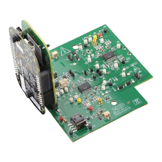
Page 7: Board Description
UM11729 NXP Semiconductors FRDMGD3162HBIEVM half-bridge evaluation board 4.4 Board description The FRDMGD3162HBIEVM is a half-bridge evaluation board populated with two GD3162 single channel IGBT or SiC gate drive devices. The board supports connection to an FRDM-KL25Z microcontroller for SPI communication configuration programming and monitoring. - Page 8 UM11729 NXP Semiconductors FRDMGD3162HBIEVM half-bridge evaluation board Figure 3. Evaluation board voltage and interface domains Table 2. Low-voltage domain 24-pin connector definitions Name Function AOUTL analog output duty cycle encoded signal (low side) for reading temperature via TSENSEA or voltage via AMUXIN GS_ENH gate strength enable HIGH;...
-
Page 9: Test Point Definitions
UM11729 NXP Semiconductors FRDMGD3162HBIEVM half-bridge evaluation board Table 2. Low-voltage domain 24-pin connector definitions ...continued Name Function INTAL fault reporting and real time V and VGE monitoring (low side) MOSIH master out slave in (high side) INTAH fault reporting and real time V... - Page 10 UM11729 NXP Semiconductors FRDMGD3162HBIEVM half-bridge evaluation board Table 3. Test point definitions Test point Definition Low-voltage domain VSUP DC voltage source connection point for VSUP power input of GD3162 devices. Externally supplied 12 V DC supply voltage. VSUP supplies 5 V regulator for gate drive VDD.
-
Page 11: Power Supply And Jumper Configuration
UM11729 NXP Semiconductors FRDMGD3162HBIEVM half-bridge evaluation board 4.4.3 Power supply and jumper configuration Figure 5. Power supply and jumper configuration Table 4. Jumper definitions Jumper Position Function PWMHSEL (J10) dead time fault protection enabled (high side) dead time fault protection disabled (use for short-circuit testing) -
Page 12: Bottom View
UM11729 NXP Semiconductors FRDMGD3162HBIEVM half-bridge evaluation board Table 4. Jumper definitions ...continued Jumper Position Function PS_EN (J6) MCU control of flyback supply enable flyback supply enable tied to VSUP adjusts VCCH and VCCL level adjusts negative VEEL level adjusts negative VEEH level 4.4.4 Bottom view... -
Page 13: Gate Drive Resistors
UM11729 NXP Semiconductors FRDMGD3162HBIEVM half-bridge evaluation board 4.4.5 Gate drive resistors • RGH - gate high resistors in series with GH_1 (strong gate charge/turn-on pin) and GH_2 (weak gate charge/turn-on pin) and HybridPACK Drive module gate. These gate drive output pins control the turn on of the SiC MOSFET gate and are enabled when PWM is logic HIGH and setting match GS_ENH. -
Page 14: Led Interrupt Indicators
UM11729 NXP Semiconductors FRDMGD3162HBIEVM half-bridge evaluation board 4.4.6 LED interrupt indicators Figure 8. LED interrupt indicators Table 5. LED interrupt indicators Description Low-side INTB connected to the INTB output pin of low-side driver indicating reported fault status when on (active LOW) High-side INTB... -
Page 15: Kinetis Kl25Z Freedom Board
UM11729 NXP Semiconductors FRDMGD3162HBIEVM half-bridge evaluation board 4.5 Kinetis KL25Z Freedom board The Freedom KL25Z is an ultra low-cost development platform for Kinetis L series MCU built on Arm Cortex-M0+ processor. Figure 9. Freedom development platform UM11729 All information provided in this document is subject to legal disclaimers. -
Page 16: To 5.0 V Translator Board
UM11729 NXP Semiconductors FRDMGD3162HBIEVM half-bridge evaluation board 4.6 3.3 V to 5.0 V translator board KITGD316xTREVB translator enables level shifting of signals from MCU 3.3 V to 5.0 V SPI communication. Figure 10. Translator board Table 6. Translator board jumper definitions Jumper... -
Page 17: Configuring The Hardware
UM11729 NXP Semiconductors FRDMGD3162HBIEVM half-bridge evaluation board Configuring the hardware FRDMGD3162HBIEVM is connected to compatible SiC MOSFET HybridPACK Drive module with a DC link capacitor as shown in Figure 11. Double pulse and short-circuit testing can be conducted utilizing Windows based PC with FlexGUI software. -
Page 18: Installation And Use Of Software Tools
UM11729 NXP Semiconductors FRDMGD3162HBIEVM half-bridge evaluation board Figure 12. Power module Installation and use of software tools Software for FRDMGD3162HBIEVM is distributed with the FlexGUI tool (available on NXP.com). Necessary firmware comes pre-installed on the FRDM-KL25Z with the kit. Even if the user intends to test with other software or PWM, it is recommended to install this software as a backup or to help debugging. -
Page 19: Configuring The Frdm-Kl25Z Microcode
UM11729 NXP Semiconductors FRDMGD3162HBIEVM half-bridge evaluation board 6.2 Configuring the FRDM-KL25Z microcode Figure 13. FRDM-KL25Z setup and interface By default, the FRDM-KL25Z delivered with this kit is preprogrammed with the current and most up-to-date firmware available for the kit. A way to check quickly that the microcode is programmed and the board is functioning properly, is to plug the KL25Z into the computer, open FlexGUI, and verify that the software version at the bottom is 6.4 or later (see... -
Page 20: Using The Flexgui
UM11729 NXP Semiconductors FRDMGD3162HBIEVM half-bridge evaluation board 7. With the KL25Z still plugged through the OpenSDA port, copy/drag-and-drop the .bin file into the KL25Z device memory. Once done, disconnect the USB for OpenSDA port and plug into the other USB port, labeled KL25Z. - Page 21 UM11729 NXP Semiconductors FRDMGD3162HBIEVM half-bridge evaluation board FlexGUI settings • Access settings by selecting Settings from the File menu Figure 15. GUI settings menu UM11729 All information provided in this document is subject to legal disclaimers. © NXP B.V. 2022. All rights reserved.
- Page 22 UM11729 NXP Semiconductors FRDMGD3162HBIEVM half-bridge evaluation board • The Loader and Logs settings are shown below: Figure 16. Loader settings Figure 17. Logs settings UM11729 All information provided in this document is subject to legal disclaimers. © NXP B.V. 2022. All rights reserved.
- Page 23 UM11729 NXP Semiconductors FRDMGD3162HBIEVM half-bridge evaluation board • Access settings by selecting Settings from the File menu. • The Register Map and Tabs settings are shown below: Figure 18. Register map settings Figure 19. Tabs settings UM11729 All information provided in this document is subject to legal disclaimers.
- Page 24 UM11729 NXP Semiconductors FRDMGD3162HBIEVM half-bridge evaluation board Command Log window • The Command Log area informs the user about application events. Figure 20. Command Log area UM11729 All information provided in this document is subject to legal disclaimers. © NXP B.V. 2022. All rights reserved.
- Page 25 UM11729 NXP Semiconductors FRDMGD3162HBIEVM half-bridge evaluation board Global workspace controls • Always visible in the lower left corner of the main application window. – GD3162 tab functionality – Switch modes between run and configuration mode – Set SPI frequency Figure 21. Device pins settings and status menus UM11729 All information provided in this document is subject to legal disclaimers.
- Page 26 UM11729 NXP Semiconductors FRDMGD3162HBIEVM half-bridge evaluation board • Pins tab functionality – Set control levels. Default values are shown. – Read and automatically poll INTB pins (INTA pins are added for GD3162). – Control pins set values to a default to a functional state.
- Page 27 UM11729 NXP Semiconductors FRDMGD3162HBIEVM half-bridge evaluation board • Status tab functionality – Monitors Status 1 and Status 2 fault bits. Bits that are set are shown in red. – Ability to clear all faults and automatically poll status registers. Figure 23. Status tab functionality •...
- Page 28 UM11729 NXP Semiconductors FRDMGD3162HBIEVM half-bridge evaluation board • Gate strength tab functionality – Read and poll the pull-up and pull-down gate strength that can either be controlled by GSSPI_EN set to logic 1 in MODE2 register and bit settings in config register STATCON4 –...
- Page 29 UM11729 NXP Semiconductors FRDMGD3162HBIEVM half-bridge evaluation board Register map • Registers are grouped according to function; independent lines to read and write the registers • Individual registers can be read by clicking the R button and can be written by using the W button.
- Page 30 UM11729 NXP Semiconductors FRDMGD3162HBIEVM half-bridge evaluation board Gate Drive tab • Allows setting of parameters related to the gate drive; controls are disabled when not in config mode • Provides a more intuitive visual way to set parameters • All settings are automatically synchronized with the register controls.
- Page 31 UM11729 NXP Semiconductors FRDMGD3162HBIEVM half-bridge evaluation board Current Sense tab • Allows setting of parameters related to current sense • Provides a more intuitive visual way to set parameters • All settings are automatically synchronized with the register controls. Figure 28. Current sense tab UM11729 All information provided in this document is subject to legal disclaimers.
- Page 32 UM11729 NXP Semiconductors FRDMGD3162HBIEVM half-bridge evaluation board DESAT & Seg Drive tab • Allows setting of parameters related to desat and segmented drive • Provides a more intuitive visual way to set parameters • All settings are automatically synchronized with the register controls.
- Page 33 UM11729 NXP Semiconductors FRDMGD3162HBIEVM half-bridge evaluation board Overtemperature tab • Allows setting of parameters related to overtemperature and overtemperature warning thresholds • Provides a more intuitive visual way to set parameters • All settings are automatically synchronized with the register controls.
- Page 34 UM11729 NXP Semiconductors FRDMGD3162HBIEVM half-bridge evaluation board Undervoltage and overvoltage threshold tab • Allows setting of parameters related to undervoltage and overvoltage threshold • Provides a more intuitive visual way to set parameters • All settings are automatically synchronized with the register controls.
- Page 35 UM11729 NXP Semiconductors FRDMGD3162HBIEVM half-bridge evaluation board Measurements tab • Allows monitoring and graphing of ADC and temperature values Figure 32. Measurements tab UM11729 All information provided in this document is subject to legal disclaimers. © NXP B.V. 2022. All rights reserved.
- Page 36 UM11729 NXP Semiconductors FRDMGD3162HBIEVM half-bridge evaluation board Status tab • Allows monitoring of Status 1, Status 2, and Status 3 register values • Status 1 and Status 2 faults can be cleared • Status mask registers can be modified when in configuration mode •...
-
Page 37: Troubleshooting
UM11729 NXP Semiconductors FRDMGD3162HBIEVM half-bridge evaluation board Pulse tab • Used for double pulse, short circuit, and PWM testing • Select desired T1, T2, and T3 timings for each test type; select enable then generate pulses Figure 34. Pulse tab 6.4 Troubleshooting Some common issues and troubleshooting procedures are detailed below. - Page 38 UM11729 NXP Semiconductors FRDMGD3162HBIEVM half-bridge evaluation board Problem Evaluation Explanation Corrective action(s) No PWM output (fault reported) Check VGE fault (VGE_FLT) A short on IGBT or SiC module gate, Clear VGE_FLT bit (STATUS2) to or too low of VGEMON delay setting continue.
-
Page 39: Schematics, Board Layout, And Bill Of Materials
UM11729 NXP Semiconductors FRDMGD3162HBIEVM half-bridge evaluation board Problem Evaluation Explanation Corrective action(s) VREFUV reported on startup Check HV domain is powered Related to slow rise time of VCC Clear VREFUV bit (STATUS2). correctly supply on HV domain, or failed VREF... -
Page 40: Legal Information
NXP Semiconductors. whatsoever (including without limitation, all damages referenced above and In no event shall NXP Semiconductors be liable for any indirect, incidental, all direct or general damages), the entire liability of NXP Semiconductors, punitive, special or consequential damages (including - without limitation - its affiliates and their suppliers and customer’s exclusive remedy for all of... - Page 41 UM11729 NXP Semiconductors FRDMGD3162HBIEVM half-bridge evaluation board NXP — wordmark and logo are trademarks of NXP B.V. 9.3 Trademarks Kinetis — is a trademark of NXP B.V. SafeAssure — is a trademark of NXP B.V. Notice: All referenced brands, product names, service names, and trademarks are the property of their respective owners.
- Page 42 UM11729 NXP Semiconductors FRDMGD3162HBIEVM half-bridge evaluation board Tables Tab. 1. Device features ..........6 Tab. 4. Jumper definitions ........... 11 Tab. 2. Low-voltage domain 24-pin connector Tab. 5. LED interrupt indicators ........14 definitions ............8 Tab. 6. Translator board jumper definitions ....16 Tab.
-
Page 43: Table Of Contents
UM11729 NXP Semiconductors FRDMGD3162HBIEVM half-bridge evaluation board Contents Important notice ..........3 FRDMGD3162HBIEVM .........3 Getting started ............ 4 Kit contents/packing list ........4 Required equipment .......... 5 System requirements .........5 Getting to know the hardware ......5 Overview ............5 Board features ...........
Need help?
Do you have a question about the SAFE ASSURE UM11729 and is the answer not in the manual?
Questions and answers