Table of Contents
Advertisement
Quick Links
UM11623
PCA9959HN-ARD evaluation board
Rev. 1 — 21 May 2021
Document information
Information
Content
Keywords
PCA9959HN, SPI, Arduino port, EVK, LED, LED driver
Abstract
The PCA9959HN-ARD evaluation board is a daughter card equipped with
Arduino ports, designated for easy test and design of the PCA9959HN IC, 24-
channel SPI serial bus 63 mA / 5.5 V constant current LED driver. The board
is fully compliant with IMXRT1050-EVKB, LPCXpresso55S69 (LPC55S69-
EVK) and i.MX 8M Mini LPDDR4 EVK (8MMINILPD4-EVK, 8MMINID4-EVK),
including GUI software control. The board can be attached to any device
equipped with Arduino ports.
User manual
Advertisement
Table of Contents

Subscribe to Our Youtube Channel
Related Manuals for NXP Semiconductors UM11623


Summary of Contents for NXP Semiconductors UM11623
- Page 1 UM11623 PCA9959HN-ARD evaluation board Rev. 1 — 21 May 2021 User manual Document information Information Content Keywords PCA9959HN, SPI, Arduino port, EVK, LED, LED driver Abstract The PCA9959HN-ARD evaluation board is a daughter card equipped with Arduino ports, designated for easy test and design of the PCA9959HN IC, 24- channel SPI serial bus 63 mA / 5.5 V constant current LED driver.
-
Page 2: Revision History
UM11623 NXP Semiconductors PCA9959HN-ARD evaluation board Revision history Table 1. Revision history Date Description 05/05/2021 Initial version UM11623 All information provided in this document is subject to legal disclaimers. © NXP B.V. 2021. All rights reserved. User manual Rev. 1 — 21 May 2021... -
Page 3: Introduction
PCA9959HN, a 24-channel SPI serial bus 63 mA / 5.5 V constant current LED driver produced by NXP Semiconductors. The evaluation board serves as a daughter card that can be connected through an Arduino port to various Arduino compatible (including original Arduino Uno R3) EVK / motherboards for testing and measuring the characteristics of the PCA9959HN Device Under Test (DUT). -
Page 4: Kit Contents
UM11623 NXP Semiconductors PCA9959HN-ARD evaluation board 4.1 Kit contents • Assembled and tested evaluation board in an anti-static bag • Quick Start Guide 4.2 Assumptions Familiarity with the SPI bus is helpful but not required. 4.3 Static handling requirements CAUTION This device is sensitive to ElectroStatic Discharge (ESD). -
Page 5: Getting To Know The Hardware
UM11623 NXP Semiconductors PCA9959HN-ARD evaluation board Getting to know the hardware 5.1 PCA9959HN-ARD features • Combined Arduino port/Fuji connector for data and power • Multiple board connections in stack architecture • Onboard LEDs for all 24 outputs of the DUT IC •... -
Page 6: Block Diagram
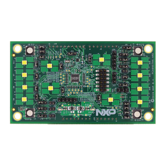
UM11623 NXP Semiconductors PCA9959HN-ARD evaluation board Figure 2. PCA9959HN-ARD board (top view) Figure 3. PCA9959HN-ARD board (bottom view) 5.3 Block diagram Figure 4 shows a block diagram of the PCA9959HN-ARD daughter board. The block diagram includes Arduino interface (J5, J6, J35, and J36 connectors) and the data lines connected to the port. -
Page 7: Arduino Port
UM11623 NXP Semiconductors PCA9959HN-ARD evaluation board (see Section 5.5 "Fuji connectors"). J46 is the Fuji output connector (pin header) and is located on the top layer of the board. J46 is intended to be mated with a similar Fuji input connector (J47) on a board mounted directly on top of the first board. In this way, several boards can be connected in a stack. -
Page 8: Fuji Connectors
UM11623 NXP Semiconductors PCA9959HN-ARD evaluation board Table 2. Pin chart of Arduino connectors and their usage ...continued Ref Des Arduino label PCA9959HN-ARD function Not used Not used Not used J35 (analog, digital, Not used A4 / SDA Not used A5 / SCL... -
Page 9: Spi Bus
UM11623 NXP Semiconductors PCA9959HN-ARD evaluation board Table 3. Pin chart of Fuji connectors and their functions ...continued J46 Fuji output connector (top) J47 Fuji input connector (top) SDO (U2) distribution to next board SDI SDO (U2) from previous board (U2) OE distribution... -
Page 10: Control Bus
UM11623 NXP Semiconductors PCA9959HN-ARD evaluation board Figure 5. Location of the 0 Ω resistors R278 to R281 on the MIMXRT1050-EVK board 5.7 Control bus The control bus contains three additional control lines (purple color in Figure 4): OE (Output Enable), RESET, and I MAX. OE and RESET are routed to the OE and RESET inputs of the DUT, directly from Arduino port for the first (or base daughter board) and through Fuji connectors for the additional boards (pin 5, and pin 7). -
Page 11: Schematic, Board Layout And Bill Of Materials
UM11623 NXP Semiconductors PCA9959HN-ARD evaluation board on the type of EVK being used and the current rating of the Arduino/Fuji connectors (approx. 4.5 A). The current limitation as a function of the EVK is as follows: • IMXRT1050 EVK: – EVK powered from USB: limited by the current rating of the USB connector – max. 2 boards –... -
Page 12: Installing And Configuring Software Tools
UM11623 NXP Semiconductors PCA9959HN-ARD evaluation board Installing and configuring software tools PCA9959HN-ARD evaluation board is designed and built as a daughter board able to work with a mother board equipped with an Arduino port. The board was built to be fully compatible with the following NXP evaluation boards: •... -
Page 13: Configuring The Hardware
UM11623 NXP Semiconductors PCA9959HN-ARD evaluation board Configuring the hardware 7.1 Using the PCA9959HN-ARD with MIMXRT1050-EVK board Figure 6 shows the required hardware for operation of the PCA9959HN-ARD daughter board with MIMXRT1050-EVK. The following hardware is necessary when working with this kit: •... -
Page 14: Using The Pca9959Hn-Ard With An Lpcxpresso55S69 Development Board
UM11623 NXP Semiconductors PCA9959HN-ARD evaluation board 3. Insert the PCA9959HN-ARD daughter card into the Arduino connector on the EVK. Figure 4. Using USB connector J28, connect the EVK board to a USB port on the computer. 5. Install the IMXRT1050 target firmware (download from NXP site and see UM11581 step-by-step instructions). - Page 15 UM11623 NXP Semiconductors PCA9959HN-ARD evaluation board Figure 8. PCA9959HN-ARD daughter board and LPCXpresso55S69 mother board The following steps describe how to assemble, power up, program, and operate the configuration shown in Figure 1. Insert the PCA9959HN-ARD daughter card to P16 – P19 connectors located on LPCXpresso55S69 development board (see the marked pins of P16 –...
-
Page 16: Using The Pca9959Hn-Ard With An I.mx 8M Mini Lpddr4 Evk
UM11623 NXP Semiconductors PCA9959HN-ARD evaluation board 4. Install GUI application on PC (see UM11581, Arduino shields GUI and firmware installation manual). 5. Open the GUI application to operate the device from the PC. For details regarding GUI operation, see Section 8 "GUI description". - Page 17 UM11623 NXP Semiconductors PCA9959HN-ARD evaluation board • One USB-A / USB Micro-B cable • A PC with Windows 10 operating system It is recommended to attach the PCA9959HN-ARD to the Arduino connectors of the IMX8MMINI-IARD interposer board first, and then the resulting assembly to the i.MX 8M Mini LPDDR4 EVK.
-
Page 18: Using The Pca9959Hn-Ard With Another Device
UM11623 NXP Semiconductors PCA9959HN-ARD evaluation board 5. Place SW101 in the ON position to power-up the boards. 6. Install the MIMXRT1050 target firmware (download from NXP site and see UM11581 for step-by-step instructions). 7. Install GUI application on PC (see... -
Page 19: Gui Description
NXP Semiconductors PCA9959HN-ARD evaluation board GUI description A GUI application is available for the three EVK boards from NXP Semiconductors. The application is common for all EVKs/development boards. This section describes the GUI application and how the user can control the PCA9959HN-ARD daughter board from the graphical interface. - Page 20 UM11623 NXP Semiconductors PCA9959HN-ARD evaluation board • Select COM Port displays the port selected for the communication. The port is automatically selected by the system and is shown here as (COM3, Figure 12). • Select Board allows the user to select the correct daughter board (the application can support three different boards).
-
Page 21: Global
UM11623 NXP Semiconductors PCA9959HN-ARD evaluation board 8.2 Global Figure 13. Graphical interface – Global tab activated The Global tab contains four secondary tabs. The default secondary tab is Grid Duration (see the red arrows in Figure 13). The four secondary tabs set four internal registers of PCA9959 device. - Page 22 UM11623 NXP Semiconductors PCA9959HN-ARD evaluation board Figure 15. Graphical interface – Global / Gradation tab activated Figure 16. Graphical interface – Global / Side tab activated UM11623 All information provided in this document is subject to legal disclaimers. © NXP B.V. 2021. All rights reserved.
-
Page 23: Channels
UM11623 NXP Semiconductors PCA9959HN-ARD evaluation board 8.3 Channels Figure 17. Graphical interface – Channels / Errors tab activated When Channels tab is activated, the displayed secondary tabs differ as a function of shows the Channels the value set for PAGE_SEL register (see Figure 14). - Page 24 UM11623 NXP Semiconductors PCA9959HN-ARD evaluation board Figure 18. Graphical interface – Channels / Grid tab activated Table 6. Secondary tabs under Channels – PAGE_SEL 1 Register name Register HEX Remarks Errors (Figure EFLAG0 to EFLAG5 #02h – #07h Read only Group Config...
- Page 25 UM11623 NXP Semiconductors PCA9959HN-ARD evaluation board Figure 19. Graphical interface – Channels / Group Config tab activated UM11623 All information provided in this document is subject to legal disclaimers. © NXP B.V. 2021. All rights reserved. User manual Rev. 1 — 21 May 2021...
- Page 26 UM11623 NXP Semiconductors PCA9959HN-ARD evaluation board Figure 20. Graphical interface – Channels / Preset Current 1 tab activated UM11623 All information provided in this document is subject to legal disclaimers. © NXP B.V. 2021. All rights reserved. User manual Rev. 1 — 21 May 2021...
- Page 27 UM11623 NXP Semiconductors PCA9959HN-ARD evaluation board Figure 21. Graphical interface – Channels / Preset Current 2 tab activated UM11623 All information provided in this document is subject to legal disclaimers. © NXP B.V. 2021. All rights reserved. User manual Rev. 1 — 21 May 2021...
-
Page 28: Operation Example
UM11623 NXP Semiconductors PCA9959HN-ARD evaluation board Figure 22. Graphical interface – Channels / Preset Current 3 tab activated Operation example This section details the necessary steps to operate the PCA9959HN-ARD daughter board with one of three EVKs from the GUI. This helps the user for a quick test of the board and to understand the register functionality. -
Page 29: Abbreviations
UM11623 NXP Semiconductors PCA9959HN-ARD evaluation board then click WriteAll button. This command sets all GD[x]G[y] internal registers with the “Preset Current 1” value. 11. Click Global → Page Select (see Figure 13). From the interface set the value “1” for bit 7 (in the displayed byte is the only active bit), and then click Write. -
Page 30: Legal Information
NXP Semiconductors. In no event shall NXP product remains with customer. In no event shall NXP Semiconductors, its... - Page 31 UM11623 NXP Semiconductors PCA9959HN-ARD evaluation board Tables Tab. 1. Revision history ..........2 Tab. 5. Secondary tabs under Channels – PAGE_ Tab. 2. Pin chart of Arduino connectors and their SEL 0 .............. 23 usage ..............7 Tab. 6. Secondary tabs under Channels – PAGE_ Tab.
-
Page 32: Table Of Contents
'Legal information'. © NXP B.V. 2021. All rights reserved. For more information, please visit: http://www.nxp.com For sales office addresses, please send an email to: salesaddresses@nxp.com Date of release: 21 May 2021 Document identifier: UM11623...
Need help?
Do you have a question about the UM11623 and is the answer not in the manual?
Questions and answers