
Related Manuals for urmet domus 1098/318


Summary of Contents for urmet domus 1098/318
- Page 1 Mod. 1098 DS1098-019A NVR H.265 WITH HDMI NVR 4K H.265 PRO SERIES 8 Ch. Ref. 1098/318 16 Ch. Ref. 1098/316 16 Ch. with PoE Ref. 1098/316P 32 Ch. Ref. 1098/332 USER MANUAL...
-
Page 2: Table Of Contents
Front panel NVR Ref. 1098/316 and Ref. 1098/316P ................... 9 2.1.3 Front panel NVR Ref. 1098/332 ........................9 Rear Panel ..........................10 2.2.1 Rear panel NVR Ref. 1098/318 and Ref. 1098/316 ..................10 2.2.2 Rear panel NVR Ref. 1098/316P ........................ 10 2.2.3 Rear panel NVR Ref. 1098/332........................10 2.2.4... - Page 3 3.4.10 Device (HDD) .............................. 42 3.4.10.1 HDD settings ............................42 3.4.10.2 Disk Group ............................... 43 3.4.10.3 S.M.A.R.T. (Self-Monitoring, Analysis and Reporting Technology) information ......... 44 3.4.10.4 PTZ settings ............................. 44 3.4.10.5 AF Controls for Auto Focus IP Camera Models ..................45 3.4.10.6 Cloud Storage ............................
- Page 4 NVR Specifications Rev. 1098/318-1098/316-1098/332 (Pal Format) ..........111 NVR Specifications Rev. 1098/316P (Pal Format) ................112 Maximum recording time with a 2000GB Hard Disk ................. 113 Ref. 1098/318 – 1098/316 – 1098/316P – 1098/332 ............113 Recording alarm setting ........................119 Troubleshooting ........................... 119 Maintenance ............................
-
Page 5: General Information
Dear Customer, Thank you for purchasing this product. This quick start guide was written to help you set up the URMET S.p.A NVR PRO Series models Ref.1098/318 - Ref.1098/316 – Ref. 1098/316P – Ref. 1098/332 quickly and easily. This manual should be read before using the equipment as it contains information for its correct and safe use. -
Page 6: Opening The Package
1.2.1 PACKAGE CONTENTS Power supply unit INPUT 100-240 Vac 50/60Hz 1.5 A max ⇒ • OUTPUT 12Vcc 5A for Ref.1098/318 Ref. 1098/316 Ref. 1098/332 ⇒ • 48Vcc 2A per Ref. 1098/316P ⇒ Shuko plug Italian plug One mouse One I.R. remote control (2 AAA batteries included) LAN CAT.5 crossover network cable... -
Page 7: Warnings
WARNINGS 1.3.1 POWER SUPPLY Check mains rating before plugging the power unit in. Do not pull on the cord to unplug the device. Switch the device off before unplugging power unit. This operation must not be performed when the NVR Boost 3.0 Series is recording or playing or when the configuration menu is open. -
Page 8: Recording Images
PRIVACY AND COPYRIGHT The digital video recorder Series PRO Ref. 1098/318- Ref. 1098/316- Ref. 1098/316P – Ref. 1098/332 is a device for CCTV systems. The recording of images is subject to the laws in force in the country of use. Recording of images protected by copyright is forbidden. -
Page 9: Description Of The Parts
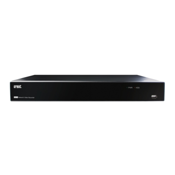
DESCRIPTION OF THE PARTS FRONT PANEL NVR stands for Network Video Recorder. 2.1.1 FRONT PANEL NVR REF. 1098/318 2.1.2 FRONT PANEL NVR REF. 1098/316 AND REF. 1098/316P 2.1.3 FRONT PANEL NVR REF. 1098/332 Writing or Number Symbol Function and description... -
Page 10: Rear Panel
REAR PANEL 2.2.1 REAR PANEL NVR REF. 1098/318 AND REF. 1098/316 2.2.2 REAR PANEL NVR REF. 1098/316P 2.2.3 REAR PANEL NVR REF. 1098/332 Number Physical port Connection method Power switch Power on and off Power connector Power supply connector Sensor/Alarm Sensor or alarm device connector USB 2.0 port... -
Page 11: Sensor/Alarm Functions
2.2.4 SENSOR/ALARM FUNCTIONS Alarm input: connect the sensor [-] signal to pin G (GND) and the [+] signal to the input of channel 1…8, as alarm device. Alarm output: connect the two “ALARM” signals. REMOTE CONTROL Button name Button function Channel 1-8 selection;... -
Page 12: Mouse Operation
MOUSE OPERATION In addition to the buttons on the front panel and the remote control, the system can also be operated using a mouse. TYPE Function In locked menu mode, open the pop-up menu and click on any submenu to open the login window;... -
Page 13: System Initialisation
SYSTEM INITIALISATION Plug the power supply cable of the NVR into the wall socket, insert the power connector in the rear panel and press the Power button (if included) on the rear panel to open the system initialisation screen shown above. LIVE INTERFACE AND POP-UP MENU The <Live>... - Page 14 Stream Switch (Main Stream, Sub Stream) • Start Manual Record • Instant Playback • Zoom • Colour Settings • • Fish Eye management (only available if a fish eye camera is connected) • Note: when the hard disk (HDD) is not connected or an error has occurred, the “H” character appears on the first channel of the live screen and an audible alarm may sound.
-
Page 15: Guide To The Main Menu
GUIDE TO THE MAIN MENU After the system has initialised, right-click on the main interface to access the pop-up menu. At this point, you can set parameters and select Main Menu, Multi-Pics, Stream Switch, Preview Policy, Playback, Mute, Start Sequence, Shutdown, etc. - Page 16 Disk Group S.M.A.R.T. Device AF Controls Cloud General General Users Info System Info Channel Info Record Info Intelligent Analysys Main Menu Schedule Maintain Events Advanced Intelligent Shutdown Shutdown Reboot DS1098-019A...
-
Page 17: Main Menu
MAIN MENU To access the Main Menu, enter the Password “00000000” to log in for the first time. The password can be personalised [Main Menu System Users]. later in In <Live> mode, click on the [Menu] button on the remote control to open the Main Menu interface, as shown in section 2.1. -
Page 18: Display
3.4.1 DISPLAY 3.4.1.1 IP Channels (IP cameras) Select the [Add All] function to add the IP camera quickly to the LAN or select the [+] button to manually add the IP camera connected to the LAN network. Enter the correct password of the IP camera (default: admin) after having selected the [Add All] button and confirm the operation. - Page 19 Adding a user Go to [Main menu Parameter Display IP Channels] and select [User-defined add]. Click on an available camera in the list of detected devices. RTSP function The RTSP function is used to view the main/secondary stream videos of an IP camera connected to the NVR on a web page of the PC or on the local monitor via the RTSP port.
-
Page 20: Live
3.4.1.2 Live Read the descriptions under the following figure for this menu page: Channel: this is used to set the required channel. • Channel Name: this is used to set the channel name; the system accepts up to eight characters. •... -
Page 21: Output
3.4.1.3 Output Read the description under the following figures for this menu page: Video output: fixed value. Seq Mode: the layout can be set for the Sequence function. SEQ Dwell Time: time interval of the Sequence function. The default setting is 5 seconds. The user can edit this setting as required. -
Page 22: Privacy Zone
3.4.1.5 Privacy Zone This function is used to configure the privacy zone parameters as shown in the following figure. Up to four privacy zones can be selected for each channel. Proceed as follows: 1. Select the channel number. 2. Enable the Mask Area. 3. -
Page 23: Record Schedule
3.4.2.2 Record Schedule This function is used to program recording for all days of the week in continuous mode and upon alarm for each channel. Select the recording mode (Normal, Motion, Alarm) and then set the recording time on the grid. Channel: this option is used to select a desired channel. -
Page 24: Sub Stream
3.4.2.4 Sub Stream Read the description under the following figures for this menu page: Channel: this option is used to select a desired channel. • Resolution: 352x288, 640x360 and 704x576, 1280x720, 1920x1080 resolutions are supported. • FPS (Frame Rate): the following range values can be selected: PAL: 1-25 f/s; NTSC: 1-30 f/s. The Frame Rate •... -
Page 25: Capture (Cattura)
3.4.3 CAPTURE (CATTURA) This subsection of the Parameters menu can be used to configure the parameters dedicated to the acquisition of images in alarm conditions and to the programming of the times during which the function must be active. 3.4.3.1 Capture The Capture function is used to set the parameters for recording images in an alarm situation. -
Page 26: Network
3.4.4 NETWORK 3.4.4.1 Network set Read the description under the following figures for this menu page: After having selected the network mode (DHCP, PPPOE or static allocation) and set the ports, the remote NVR can be accessed via a network or the Internet. The main functions of the Network OSD Menu are: UPnP (Universal Plug and Play) function: if the router supports the UPnP function and <UPnP>... - Page 27 Press [Save] to save the changes. IMPORTANT NOTE The DNS fields must be filled in correctly for the DDNS system to work properly. Port configuration At this point, the external ports on the router must be sent to the NVR. This function is usually called “Port-forwarding” or “Virtual Server”...
- Page 28 Manual mode: if the UPnP function cannot be used, manually set port-forwarding on the port- forwarding (or virtual server) table of the router. IMPORTANT NOTE The firewall of some routers may block forwarding of the ports set on port-forwarding tables. Carefully check the firewall settings of your router.
-
Page 29: Router Port-Forwarding
3.4.4.2 Router port-forwarding Port-forwarding is needed to access the NVR connected to the router from outside of the router network. Port-forwarding is not necessary if PPPoE is selected. Enter the IP address of the router, taken from the IE browser, to open the router configuration interface shown above. -
Page 30: Email Set
3.4.4.4 Email set Click on the [Main menu Parameter Network Email] option to access the email setup interface shown here. SSL: this is a secure link transfer protocol. Via SSL it is possible to encode the communicated information (including your email) to prevent hackers from reading emails, transmitted data and even passwords. Set SSL to “On”... - Page 31 IMPORTANT NOTE Before obtaining the Urmet DDNS ID, check that the user password is enabled; otherwise, the procedure cannot be completed. Check that the DDNS function is enabled and that the URMETDDNS or URMETDDNS2 server is selected. Click on the Get button and wait for approximately 10 seconds so that the NVR ID may be generated. This is necessary for remote access via the Urmet Web portal (see following figure).
-
Page 32: Rtsp
You can register on the DDNS Service website to obtain a domain name, a user name and a password. Server: select the DDNS provider. • Host Name: enter the host domain name in the dynamic domain name system, e.g.: username.changeip.com; •... -
Page 33: Alarm
3.4.5 ALARM 3.4.5.1 Motion Read the description under the following figures for this menu page: Channel: this is used to enable/exclude the motion detection function for any channel. • Buzzer: this is used to set and program the duration of the audible signal generated when a movement is detected •... -
Page 34: 3.4.5.3 Ptz Linkage
Alarm In: this is used to select the required alarm number. • Alarm Type: this is used to select three options, i.e. NO (Normally Open), NC (Normally Closed) and OFF. By • selecting “Normally Open”, the I/O state alarm will be activated when the sensor is ON; by setting Normally Closed”, the I/O state alarm will be activated when the sensor is OFF;... -
Page 35: Occlusion Detection
3.4.5.4 Occlusion Detection Select Lens Blocking in the Alarm menu to open the following page: Select Enable to activate the Sensitivity and Send E-Mail options. Sensitivity: Set the sensitivity level (level 1~6; the higher the value, the greater the sensitivity level). When enabled, it can be used with SMTP to enable the sending of e-mail. -
Page 36: Managing A Fish Eye Camera On Playback
The playback control bar shows the current playback progress as shown below. Click at any time on the control bar to return to the previous menu if there are no recorded files at that point. 3.4.6.2 Managing a Fish Eye camera on Playback The Fish Eye functions can be managed by selecting the button on the Playback control bar, where the available views will appear (see figure below), depending on the type of Fish Eye installation that was selected for LIVE. - Page 37 Date: this selects the date for which to perform the search • Time: these two fields allow you to specify the time interval on the day for which the search is made (pre-defined time • setting 00:00:00 – 23:59:59) Channel: this selects the channel/s on which to make the search. •...
-
Page 38: Picture Search
When you press the [Search] button, the DRV gives the results of the list of recordings found in the grid. If there are numerous recordings, you can use the shift buttons at the bottom right to browse through the pages. The main available functions include: Previous Page: while viewing events, click on the button to go to the pages before the current one (except for the first page). -
Page 39: File Backup
3.4.9 FILE BACKUP There are three backup modes with which the NVR recordings can be saved on file: the first, based on the search made by date and time, is accessed by pressing the “Backup” button to the left of the Search button; this saves all the recordings recovered for the selected time period;... -
Page 40: Backup According To Event
Select the backup device (e.g. USB drive, eSATA disk or USB DVD reader) and the destination folder and press [OK] to start the backup. A progress bar is displayed in the lower part of the window to check the completion status of the Backup. 3.4.9.3 Backup according to event In the window shown below, press [Search] to start the search for the video recordings available on the hard disk... -
Page 41: Media Player Backup
When the backup is completed, click on the [OK] buttons, as shown above. Note: The file will be saved in *.264, AVI or mp4 format. • The recording files can be reproduced through the NVR Client reader. When DRL Client is installed, the system •... -
Page 42: Device (Hdd)
:Open: click on the icon to open a recording file; :Click on the icon to access full screen mode. :Click on the icon to never position a target on top. :Click on the icon to position a target on top. :Click on the icon to position the recording currently being played on top. -
Page 43: Disk Group
No.: this indicates that the HDD was not preconfigured by the system. • Type: this indicates the disc type; the possible values are: RW (Read Write), RE (Redundant), RD (Read Only) • Disk Group: Group with which the HDD was associated •... -
Page 44: Self-Monitoring, Analysis And Reporting Technology) Information
IP Channels: if this option is enabled, it can be used to add the channels related to IP cameras to the group. • Important: a camera cannot be added to two or more groups at the same time 3.4.10.3 S.M.A.R.T. (Self-Monitoring, Analysis and Reporting Technology) information Click on [Main menu Device S.M.A.R.T.] to access the interface shown below. -
Page 45: Af Controls For Auto Focus Ip Camera Models
3.4.10.5 AF Controls for Auto Focus IP Camera Models This function is used to customise the camera focusing mode. Possible options are: SEMI: focusing is performed only after the zooming operations are finished. SEMI ÷ AUTO ÷ AF MODE MANUAL ÷ OFF AUTO: focusing is adjusted automatically. -
Page 46: Dst Settings
Here you can modify the system dates and time, the date/time format, the video format and the automatic logout. 3.4.11.2 DST settings This function is used to set daylight saving time. Click on [Main Menu System General DST]. DST status and mode can be set using the interface shown above. 3.4.11.3 Network Time Protocol (NTP) Service This service is used by the NVR to synchronise the system clock with the NTP Server. -
Page 47: Users
Note: this is only possible when the system is connected to the Internet. When the NTP function is set to “Enable”, the system calibrates the time every 00:07:50 and whenever it is switched on. 3.4.11.4 Users Main Menu System Users Click on [ ] to access the interface shown below. -
Page 48: Information
[Admin] is authorised to set common user rights. Log Search: this is used to check the entire system log. • Parameter: this is used to set all parameters. • Maintain: this is used to update the version, restore default settings, restart or stop the device. •... -
Page 49: Channel Info
3.4.11.6 Channel Info Go to [ Main Menu System Channel Info ] as shown in the following figure. Here the user can view information on various connected IPCs (state, mainstream, substream, motion detection, privacy zone, cruise, etc.). 3.4.11.7 Record Info Main Menu System Record Info Go to [ ] as shown in the following figure. -
Page 50: Log Search
3.4.11.8 Log Search The last item in the System section is for running searches in the NVR log. The modes for search and Backup on USB or CD/DVD drives are basically the same as those described in paragraphs “3.4.7 - Event Search” and paragraph “3.4.9 - File Backup”... -
Page 51: Advanced
3.4.12 ADVANCED 3.4.12.1 Maintain Click on [ Main menu Advanced Maintain ] to access the interface shown below. Default User: if this parameter is set to “Admin” (default setting), the cameras can be viewed after having • initialised the NVR with the enabled Administrator password. If this parameter is set to “OFF”, the cameras will not appear after initialisation of the NVR with the enable Administrator password. - Page 52 IPC Upgrade: the IPC can be updated by means of the connected NVR. Decompress the IPC update file and • copy the *.sw file from the NVRupgrade director into the root directory of the U flash drive, as shown in the figure below —>...
-
Page 53: Events
IPC Restore: restored the focus of the IP camera auto focus (an operation not possible for an IP camera with an • ONVIF protocol). IMPORTANT NOTE You are strongly advised to back up the recording files before upgrading the firmware version. After the backup, the files may be played using the Player software contained in the old firmware version. -
Page 54: Smart Analysis
3.4.12.3 Smart analysis This section briefly describes the intelligent video analysis functions capable of generating specific events that can also be recorded on a remote NVR. For further details on the use and settings of the intelligent video analysis functions, you are recommended to visit the URMET website http://www.urmet.com for series or product codes, the availability of relevant additional material and any firmware updates describing improvements to the intelligent video analysis algorithms. -
Page 55: Shutdown
3.4.13 SHUTDOWN The device can be started or shut down after inserting the NVR password. MAIN POP-UP MENU 3.5.1 MENU LOCK To ensure system safety, click on the [ ] icon to block the system interface when exiting from the NVR. To access the NVR once more, enter the code and password for the device to unlock the interface, as shown below. -
Page 56: Start Sequence
3.5.5 START SEQUENCE After the set channel sequence time (see section 3.4.3), click on the Start Sequence icon on the tool bar to start the sequence. 3.5.6 MUTE Click on the Mute button, on the control panel or on the remote control, to switch NVR mute on and off; click on the icon on the main menu to display a vertical bar for adjusting the volume. -
Page 57: Cruise Setting
3.6.7 CRUISE SETTING The Auto Cruise function can be set on the PTZ settings menu to program the Cruise function (off by default) and to set the Cruise channel, the current point, the total quantity, the dwell time, etc. How to program a preset point: Total: this is used to program the number of preset points. -
Page 58: Display
Moving the cursor downwards brings up a drop-down multi-function Fish Eye bar, as shown in the LIVE screen above. Select the button from the multi-function Fish Eye bar to specify the type of camera installation ("Fish Eye Mode Select"): ceiling, horizontal plane, wall or inclined plane. After choosing the installation plan, select "Save" to save the type of installation chosen. -
Page 59: Ceiling Installation
3.6.8.3 Ceiling installation Select the button on the multi-function bar displayed at the bottom of the LIVE screen of the local monitor. At this point, if the fisheye camera is mounted on the ceiling, select the button from the Fish Eye installation menu, shown in the figure below, and save the settings. - Page 60 3D cylinder, as shown in the figure: 180° Panorama view, as shown in the figure: 360° Panorama view, as shown in the figure: 4PTZ, as shown in the figure: DS1098-019A...
- Page 61 Fisheye + 3PTZ (Fisheye View, the different coloured areas represent different PTZ viewing angles, select the range of the corresponding PTZ line and drag to change the viewing angle, as shown in the figure): Fisheye + 8PTZ (Fisheye View, the different coloured areas represent different PTZ viewing angles, select the range of the corresponding PTZ line and drag to change the viewing angle, as shown in the figure): DS1098-019A...
- Page 62 360° Panorama View + 3PTZ (Panorama View, the different coloured areas represent different PTZ viewing angles, select the range of the corresponding PTZ line and drag to change the viewing angle, as shown in the figure): 360° Panorama View + 8PTZ (Panorama View, the different coloured areas represent different PTZ viewing angles, select the range of the corresponding PTZ line and drag to change the viewing angle, as shown in the figure): DS1098-019A...
-
Page 63: Installation On A Horizontal Surface
3.6.8.4 Installation on a horizontal surface Select the button on the multi-function bar displayed at the bottom of the LIVE screen of the local monitor. At this point, if the fisheye camera is mounted on a horizontal surface/table, select the button from the Fish Eye installation menu, shown in the figure below, and save the settings. - Page 64 3D Cylinder view, as shown in the figure: 180° Panorama view, as shown in the figure: 360° Panorama view, as shown in the figure: DS1098-019A...
- Page 65 4PTZ, as shown in the figure: Fisheye + 3PTZ (Fisheye View, the different coloured areas represent different PTZ viewing angles, select the range of the corresponding PTZ line and drag to change the viewing angle, as shown in the figure): DS1098-019A...
- Page 66 Fisheye + 8PTZ (Fisheye View, the different coloured areas represent different PTZ viewing angles, select the range of the corresponding PTZ line and drag to change the viewing angle, as shown in the figure): 360° Panorama View + 3PTZ (Panorama View, the different coloured areas represent different PTZ viewing angles, select the range of the corresponding PTZ line and drag to change the viewing angle, as shown in the figure): DS1098-019A...
-
Page 67: Wall Installation
360° Panorama View + 8PTZ (Panorama View, the different coloured areas represent different PTZ viewing angles, select the range of the corresponding PTZ line and drag to change the viewing angle, as shown in the figure): 3.6.8.5 Wall installation Select the button on the multi-function bar displayed at the bottom of the LIVE screen of the local monitor. - Page 68 VR view, double click with the right mouse button to begin navigation; Normal Panorama view, as shown in the figure: 4PTZ DS1098-019A...
- Page 69 Fisheye + 3PTZ (Fisheye View, the different coloured areas represent different PTZ viewing angles, select the range of the corresponding PTZ line and drag to change the viewing angle, as shown in the figure): Fisheye + 8PTZ (Fisheye View, the different coloured areas represent different PTZ viewing angles, select the range of the corresponding PTZ line and drag to change the viewing angle, as shown in the figure): DS1098-019A...
- Page 70 Panorama View + 3PTZ (Panorama View, the different coloured areas represent different PTZ viewing angles, select the range of the corresponding PTZ line and drag to change the viewing angle, as shown in the figure): Panorama View + 8PTZ (Panorama View, the different coloured areas represent different PTZ viewing angles, select the range of the corresponding PTZ line and drag to change the viewing angle, as shown in the figure): DS1098-019A...
-
Page 71: Installation On An Inclined Plane
3.6.8.6 Installation on an inclined plane Select the button on the multi-function bar displayed at the bottom of the LIVE screen of the local monitor. At this point, if the fisheye camera is mounted on an inclined plane, select the button from the Fish Eye installation menu, shown in the figure below, and save the settings. - Page 72 Normal Panorama view, as shown in the figure: Fisheye + 3PTZ (Fisheye View, the different coloured areas represent different PTZ viewing angles, select the range of the corresponding PTZ line and drag to change the viewing angle, as shown in the figure): DS1098-019A...
- Page 73 Fisheye + 8PTZ (Fisheye View, the different coloured areas represent different PTZ viewing angles, select the range of the corresponding PTZ line and drag to change the viewing angle, as shown in the figure): 4PTZ and Panorama view + 3PTZ (Panorama view, the different coloured areas represent different PTZ viewing angles, select the range of the corresponding PTZ line and drag to change the viewing angle, as shown in the figure): DS1098-019A...
- Page 74 Panorama View + 8PTZ (Panorama View, the different coloured areas represent different PTZ viewing angles, select the range of the corresponding PTZ line and drag to change the viewing angle, as shown in the figure): DS1098-019A...
-
Page 75: Web Interface Plug-In Download And Installation
WEB INTERFACE PLUG-IN DOWNLOAD AND INSTALLATION Open the web browser and enter the IP address and the NVR web port, i.e.: http://IP Address:Web Port/. The ActiveX plug-in will be automatically downloaded and installed when the computer is connected to the Internet. User rights may need to be set if the computer uses the Vista operating system. -
Page 76: Access To The Nvr Web Interface Via Ip Address, Url Or Urmet Ddns Account
ACCESS TO THE NVR WEB INTERFACE VIA IP ADDRESS, URL OR URMET DDNS ACCOUNT Follow the instructions for configuring and accessing the web pages of the device on Internet Explorer. The web can be accessed in three ways: Direct access via LAN network: start Internet Explorer and type the IP address and the HTTP port of the NVR on the address bar, as follows: http://IP Address:HTTP Port (i.e., http://192.168.36.40:85). -
Page 77: Live Interface
LIVE INTERFACE After accessing the Web Manager, you can enter the Live interface as shown below. 4.2.1 MENU BAR The menu bar includes the [Live], [Replay], [Configuration], [Path Configuration] and [Logout] options. 4.2.2 LIVE DISPLAY Once the Web Application Manager has been started on the local PC, the system will open the <Live> interface shown above by default. -
Page 78: Managing Fish Eye Cameras
: CH Display Mode : This is used to open all channels in <live> mode. : This is used to close all channels in <live> mode. : 4:3 view : Normal view (fit to page) : Click on the icon to display the current window in full screen mode; right-click to see the menu option and select <Exit full screen>. -
Page 79: Ptz Control
4.2.4 PTZ CONTROL Select the icon (top right) to open the PTZ interface. PTZ movement direction control: this allows you to control the direction of the PTZ camera. The central button is the [Auto-cruise] control. PTZ speed control bar : Iris, Focus and Zoom control : Set (+)/Delete (-) preset;... -
Page 80: Video Control
4.2.5 VIDEO CONTROL Select the icon (top right) to open the colour settings interface. Hue: This adjusts the video hue; Bright: This adjusts the video brightness; Contrast: This adjusts the video contrast; Saturation: This adjusts the video saturation; This restores the default colour settings. This updates the colour settings of the saved video. -
Page 81: Playback
PLAYBACK Click on the [ ] icon to access the <playback> interface, shown below. The Web Application Manager supports simultaneous playback of up to four channels. 4.3.1 RECORD SEARCH First, select the date you wish to check, then tick <Synchronous Playback> and the channels you wish to play, as shown below. -
Page 82: Playback Control
You can select either Main Stream or Sub Stream playback if the Dual Stream option (i.e. Main Stream + Sub Stream) was selected during recording. If the < > option is ticked, the selected channel will be played synchronously; alternatively, the channels can be played back separately. -
Page 83: Snapshot Function
4.3.3 SNAPSHOT FUNCTION Move the mouse cursor on the channel you wish to acquire and click on the icon to acquire live images remotely. After having acquired the images, they can be saved in a specific path as shown below. The acquired files will be saved in *.bmp format. -
Page 84: Managing Fish Eye Cameras On Playback
4.3.5 MANAGING FISH EYE CAMERAS ON PLAYBACK Clicking the button on the Playback control bar opens the menu for selecting the Fish Eye installation (ceiling, wall, table, horizontal plane/inclined plane) and the views available, depending on the type of installation selected, on the right- hand side (as shown in the figure). -
Page 85: Configuration
CONFIGURATION Click on the [Configuration] option to access the [Config] interface, shown below, and set the Display configuration and the Record, Network, Alarm, Device and System according to the needs of the moment. 4.4.1 DISPLAY Open the [Display] option to access the sub-options: Live and Privacy zone. IP Channels: this displays information on the IPCs that have been added. - Page 86 Output: The video output settings for the local monitor can be changed via the Web interface, in particular the monitor resolution and the display mode (single, Quad, Eight, Sixteen, etc.). Image Control (if supported by the IP camera model): the IP camera parameters can be set. DS1098-019A...
-
Page 87: Record
Privacy zone: Up to four privacy zones can be selected for each channel, as shown below. For detailed parameters see section 2.4.1.3. To eliminate a privacy zone, select it and then click on the <Clear> button and then on <Save> in the right-hand corner. 4.4.2 RECORD Click on the [Record] option to access its sub-options: Record parameters, Schedule and Main stream. - Page 88 Schedule: see the local settings of the NVR for detailed parameters. Green indicates Normal record; yellow indicates Motion detection; red indicates I/O triggered record. Stream setting: this can be used to set the Mainstream, Substream and Mobile Stream parameters, as shown in the following figure.
-
Page 89: Capture
4.4.1 CAPTURE Click on the [Capture] option to access the two sub-options: Capture and Capture Schedule. You can automatically capture images based on the program or manually set the parameters, as shown in the following figures: 4.4.1 NETWORK Open the <Network> option to access its sub-options: Network, Sub stream, Email and DDNS Configuration. The model supports three types of networks: Static, DHCP and PPPoE. - Page 90 System <DHCP> as default network: this sets the network type to “DHCP”, as shown below. The respective parameters must be consistent with the local settings of the NVR. Set “PPPoE” type network: the user name and the password must be consistent with the local settings of the NVR.
- Page 91 DDNS Setting: after having requested the DDNS service (see below), the <DDNS> function can be enabled in any network type (Static, DHCP and PPPoE). At this point, the NVR can be accessed via the domain name (http://domain name: port n). The detailed parameters must be consistent with the local settings of the NVR. RTSP function: this function is used to view the LIVE video camera on a PC, using the RTSP port instead of the data port.
-
Page 92: Alarm Set
4.4.2 ALARM SET Click on the <Alarm> option to access its sub-options: Motion and I/O Alarm, as shown below. Motion Detection: this is used to configure <Sensitivity>, <Alarm out>, <Alarm record>, <Alarm Capture>, etc. The detailed parameters must be consistent with the local settings of the NVR. I/O Alarm: this is used to configure <I/O Status>, <Alarm output>, <I/O Alarm record>, <Alarm email>, etc. -
Page 93: Device
Occlusion Detection (Oscuramento Lente): Select Enable to activate the Sensitivity and Send E-Mail options: 4.4.3 DEVICE Click on the <Device> option to access its sub-options: HDD and PTZ. HDD: this is used to check the HDD state, the overwrite time and to enable recording on the ESATA interface, as The detailed parameters must be consistent with the local settings of the NVR. - Page 94 PTZ configuration: The detailed parameters must be consistent with the local settings of the NVR. It is possible to select a digital protocol (via network) or an analogue protocol (via RS-485). AF Controls for Auto focus IP Camera Models: Cloud storage (available in the future) DS1098-019A...
-
Page 95: System
4.4.4 SYSTEM Click on the <System> option to access its sub-options: General, Users and Information. General: this can be used to check the NVR language and video system and to set the system time, the data format, DST and NTP, as shown below. The detailed parameters must be consistent with the local settings of the NVR. -
Page 96: Advanced
4.4.5 ADVANCED Click on the <Advanced> option to access its sub-options: System update, Load default, Events and System maintain, etc. Firmware update: this is used to remotely update the NVR system and the IP camera connected to it (the firmware update is not available for IP cameras with ONVIF protocol), as shown below. Proceed as follows to update the system: Select the upgrade file, as shown below. - Page 97 Exception: this is used to configure the Abnormal type, Buzzer output time, Alarm email and Show message parameters, as shown below. The detailed parameters must be consistent with the local settings of the NVR. Maintain: this is used to set automatic maintenance of the NVR system remotely, as shown below. The detailed parameters must be consistent with the local settings of the NVR and the Reboot function of the NVR and IPC (the Reboot function is not available for IP cameras with ONVIF protocol).
- Page 98 Intelligent: Algorithms, programming and intelligent video analysis logs. For details on the programming of these intelligent video analysis functions, see the dedicated manual DS1093-XXX. DS1098-019A...
-
Page 99: Local Setting
LOCAL SETTING The <Local setting> option can be used to set the recording file path (Live recordings and Playback clip files), the remote file download path, the Snapshot path, the file type (H.265 and AVI) and Internal, as shown below. LOGOUT Click on the [ ] icon to go back to the access interface. -
Page 100: Mobile Software
MOBILE SOFTWARE Mobile Software is used for the iOS (iPhone, iPad) and Android platforms (Android Smartphone, Tablet). The following is a description of the Mobile Client Software. SMARTPHONE DEVICE 5.1.1 URMET IUVS PLUS MOBILE SOFTWARE Urmet iUVS plus is a TVCC application for iOS and Android on smartphones, pads and tablets that is compatible with all URMET devices, both IPCam (Codec H265) and NVR/HVR (all codecs). -
Page 101: 5.1.1.1 Live
Getting Started Download the iUVS app from the Apple Store or Google Play Store and install it. • Connect your iPhone, iPad, Android phone or Android tablet to the Internet via the 3G network or WIFI. • Start the application to access the “Live” menu. •... - Page 102 1. Open a device Select to open the device list shown below, then select one of devices in the list: all its channels will open automatically. Opening a channel When a device is selected, the list of channels appears. Select a channel, which will be displayed in the main window. Recording a live video stream You can record the stream while viewing a video in live mode.
- Page 103 Live video In live mode, selecting allows you to select channels individually or all together. PTZ Control PTZ is short for Pan-Tilt-Zoom and refers to camera movement options. Select to open PTZ mode, this will bring up the PTZ control buttons on the live page. Select the arrows to control camera movement from side to side or up and down.
-
Page 104: 5.1.1.2 Playback
5.1.1.2 Playback Select “Playback” in the main menu; the play list will be displayed. A channel from the device can be played remotely. 1. Selecting a channel Select the “Remote Playback” button to open the device list, as shown below; select a channel on a device in the list. DS1098-019A... -
Page 105: 5.1.1.3 Record
2. Selecting the date When you have selected a channel, all dates with recordings will be marked with a dot. Select a date to play the recordings from that day. 5.1.1.3 Record You can record the stream while viewing a video in live mode, as shown above. 5.1.1.4 Images Images opens a gallery of screenshot pictures. -
Page 106: 5.1.1.5 Remote Settings
5.1.1.5 Remote Settings Controls on the remote device can be enabled, such as sending e-mail and enabling recording on the device. 5.1.1.6 Alarm E-mail notification of the devices can be enabled. DS1098-019A... -
Page 107: Device
5.1.1.7 Device Add or delete a device “Device” allows you to add or delete a device and edit its properties. Select Menu and “Device” or the icon at the top right of the start screen to open the interface shown below and manually add a device To add a new device, select “+”, then Manual Adding, Import Device (via QR Code), Online Device (Device present on network): enter the name of the device, the address (IP, domain name or device ID for the DDNS Urmet account), the... -
Page 108: Help
To add a device using automatic network search: Choose the device and select “Add Device” NOTE: the Data Port (i.e. 9000) must be set up in order for the the Mobile Software to work properly. If the user does not configure the mobile device port, the iUVS Mobile Software will not work. To delete a device from list, select the name of the device you want to delete, then press the delete button next to the device name. -
Page 109: P2P Function
P2P FUNCTION Once NVR and the network cameras have been configured, for remote viewing on an iPhone or Android smartphone, download the URMET iUVS app from the relevant store. For viewing on an Apple iPad or Android tablet, download the iUVSpad app from the Apple Store or the iUVStab app from the Google Play Store. - Page 110 Fill in the “Password” field entering password (default: 00000000), then press “Save” and wait for about 10 seconds for the NVR LIVE video to automatically load. IMPORTANT NOTE: In addition to P2P mode, the IP camera can also be remotely viewed on a smartphone via the DDNS Urmet service.
-
Page 111: Nvr Specifications Rev. 1098/318-1098/316-1098/332 (Pal Format)
NVR SPECIFICATIONS REV. 1098/318-1098/316-1098/332 (PAL FORMAT) Features Function 1098/318 1098/316 1098/332 Compression formats Video: H.265 and H.264 / Audio: 8kHz*16bit ADPCM 8-CH IP Video Input/ 16-CH IP Video Input/ 32-CH IP Video Input/ 1 CH Video VGA Output 1 CH Video VGA Output... -
Page 112: Nvr Specifications Rev. 1098/316P (Pal Format)
NVR SPECIFICATIONS REV. 1098/316P (PAL FORMAT) Features Function 1098/316P Compression formats Video: H.265 and H.264 / Audio: 8kHz*16bit ADPCM 16-CH IP Video Input/ Video Inputs/Outputs 1 CH Video VGA Output (up to 1080P) 1 CH Video HDMI Output (up to 4K) Audio Inputs/Outputs 1-CH Line In RCA (2.0 Vp-p, 1kΩ) / 1-CH RCA Audio Output (2.0 Vp-p, 1kΩ) 1024*768, 1280*720, 1280*1024, 1440*900, 1920*1080, 1680*1050, 1600*1200,... -
Page 113: Maximum Recording Time With A 2000Gb Hard Disk
MAXIMUM RECORDING TIME WITH A 2000GB HARD DISK REF. 1098/318 – 1098/316 – 1098/316P – 1098/332 The following resolution options can be selected on the URMET NVR PRO series “4K”, “5Mpx”, “4Mpx”, “3,5Mpx”, “3Mpx”, “1080P”, “960P/720P” on 1/4/8/16/32 IP channels in H.264 and H.265 Codec... - Page 114 4 recording channels with 5Mpx resolution (3072x1728, 8 recording channels with 5Mpx resolution (3072x1728, 2592x1944 and 2160×2160) 2592x1944 and 2160×2160) Variables to be set H.264 Codec H.265 Codec Variables to be set H.264 Codec H.265 Codec H.264 H.265 Frame Time Time Time Time...
- Page 115 1 recording channel with 3.5Mpx resolution (2304 × 1296) 32 recording channels with 4Mpx resolution (2592 × 1520) Variables to be set H.264 Codec H.265 Codec Variables to be set H.264 Codec H.265 Codec H.264 H.265 Frame Time Time Time Time H.264 H.265...
- Page 116 8 recording channels with 3Mpx resolution (2048 × 1520) 16 recording channels with 3Mpx resolution (2048 × 1520) Variables to be set H.264 Codec H.265 Codec Variables to be set H.264 Codec H.265 Codec H.264 H.265 Frame Time Time Time Time H.264 H.265...
- Page 117 1 recording channel with 960P resolution (1280 × 960) and 720P 4 recording channels with 960P resolution (1280 × 960) and 720P resolution (1280 x 720) resolution (1280 x 720) Variables to be set H.264 Codec H.265 Codec Variables to be set H.264 Codec H.265 Codec H.264...
- Page 118 IP channels with Urmet Cloud protocol 1 recording channel with 720P resolution (1280 × 720) 4 recording channels with 720P resolution (1280 × 720) Variables to be set H.264 Codec Variables to be set H.264 Codec Bitrate Frame rate HD time HD time Bitrate Frame rate...
-
Page 119: Recording Alarm Setting
RECORDING ALARM SETTING Refer to the following table: “ ⊥ ” means “alarm only, no recording”; “AMR” means “alarm recording”; “NLR” means “normal recording”; “NOR” means “no recording”. The respective icon appears once the alarm has tripped; the following indications will appear in the presence of multiple alarms. -
Page 120: 11 Maintenance
10. Q: I cannot access the NVR Client. Why? A: Check that the network connection settings are correct and that the RJ-45 port contact is sound. Check that the account and the password have been entered correctly. 11. Q: I cannot find any recordings during playback. Why? A: Check that the HDD data line is connected correctly and that the system time is correctly set. -
Page 121: Appendix: Activex Installation
APPENDIX: ACTIVEX INSTALLATION Proceed as shown below to install an ActiveX component. Enable the IE protection configuration as shown below before activating the connection to the PC: Double-click on the icon to open Internet Explorer. Open Internet Explorer by double clicking on the icon. - Page 122 Select the “Trusted Sites” area. Click on “Sites”. The following screen will appear. At this point, add the address of the device (e.g. http://192.168.36.40 or the http://www.urmetddns.com http://urmetvcc.no- address of the URMET DDNS portal or another URL, for example ip.org ) in the “Add this website to the zone”...
- Page 123 Select “Custom Level” and check that: “Initialise and script ActiveX controls not marked as safe” is set to “Enable” or • “Prompt”. “Download signed ActiveX controls” is set to “Enable” or “Prompt”. • Press “OK” each time to confirm and exit from Internet Options mode. Continue installing Active X on Internet Explorer.
- Page 124 DS1098-019A Technical area URMET S.P.A. 10154 TORINO (ITALY) Customer service +39 VIA BOLOGNA 188/C 011.23.39.810 Tel. +39 011.24.00.000 (AUTO) http://www.urmet.com Fax +39 011.24.00.300 - 323 e-mail: info@urmet.com Made in China DS1098-019A...
Need help?
Do you have a question about the 1098/318 and is the answer not in the manual?
Questions and answers