urmet domus 1093 User Manual
4 video channel dvr h.264 cif
Hide thumbs
Also See for 1093:
- Quick manual (152 pages) ,
- User manual (104 pages) ,
- User manual/instructions (80 pages)
Table of Contents
Advertisement
Advertisement
Table of Contents

Related Manuals for urmet domus 1093


Summary of Contents for urmet domus 1093
- Page 1 Mod. 1093 DS1093-014 4 VIDEO CHANNEL DVR H.264 CIF Ref. 1093/061 USER MANUAL...
-
Page 2: Table Of Contents
INDEX General information ..........................5 Product description......................... 5 1.1.1 General features............................ 5 Opening the package ......................5 1.2.1 Contents of the package ........................5 Warnings ..........................6 1.3.1 Power ..............................6 1.3.2 Safety precautions..........................6 1.3.3 Installation precautions.......................... 6 1.3.4 Cleaning the device.......................... - Page 3 PTZ menu..........................44 5.6.1 PTZ menu basic settings ........................45 User Menu ..........................47 5.7.1 Password change..........................47 5.7.2 Adding a new user..........................48 5.7.3 Deleting a user ............................ 49 Setting menu ........................50 5.8.1 Default parameters..........................50 5.8.2 Firmware ............................. 50 5.8.3 Hard disk .............................
- Page 4 8.1.3 Control buttons ............................ 89 8.1.4 Playback interface ..........................89 Advanced software functions ....................90 8.2.1 File (F) ..............................90 8.2.2 View (V)............................... 90 8.2.3 Control (C)............................92 8.2.4 Option (P) ............................93 8.2.5 Help (H) ............................... 94 Specifications (Pal format) ........................95 Maximum recording time with 160Gb hard disk ................
-
Page 5: General Information
PRODUCT DESCRIPTION URMET Domus DVR DVS 1093/061 product is a digital video recorder capable of recording several cameras on internal hard disk while showing live camera feed at the same time. Alternatively, up to two recorded cameras can be shown at the same time. -
Page 6: Warnings
1.3.6 IMAGE RECORDING This device was designed to record images, not as a burglar alarm. URMET Domus S.p.A. cannot be held liable for loss or damage following theft sustained by the user. Make a test recording before using the device to make sure that is working correctly. Please note that URMET Domus S.p.A. -
Page 7: Privacy And Copyright
Regularly check the specific section of the manufacturer’s web site at http://www.urmetdomus.it for software upgrades. 1.3.9 FIRMWARE UPGRADES Periodically check the URMET Domus SpA Customer Service Technical Area for firmware upgrades. 1.3.10 NETWORK INSTALLATION The factory default IP address of the DVR is the following: 192.0.0.64. -
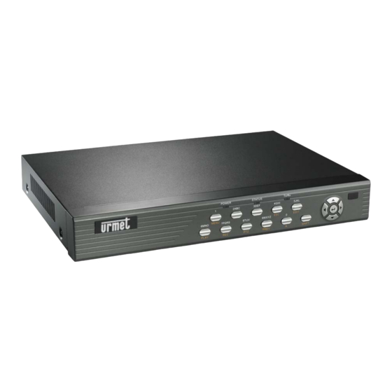
Page 8: Description Of The Parts
DESCRIPTION OF THE PARTS FRONT PANEL Figure 1: front panel Figura 2: front panel details PART DESCRIPTION IR sensor: receives the IR signals from the remote control. DVR state LED POWER • green: this indicates that the device has successfully ended initialisation operations and is ready for use STATUS •... - Page 9 In input mode, this enables numeric functions, characters and symbols SHIFT (STATUS LED on). Press SHIFT again to deactivate the functions and restore the new functions (STATUS LED off). Numeric function 0 (SHIFT on) in input mode. In LIVE mode, shows or hides the camera state bar. 0 / A →...
-
Page 10: Rear Panel
REAR PANEL Figure 3: rear panel DESCRIPTION Video input BNC sockets: these are used to connect the cameras. They have 75 Ω terminals. USB port: port for connecting a USB device for: • back-up to external hard disk • back-up to CD / DVD burner •... -
Page 11: Ir Remote Control
IR REMOTE CONTROL Figure 4: IR remote control BUTTON DESCRIPTION POWER Off button. Remote control enabling button. Numeric function 0 in input mode. → In “Preview” “Layout” menu hides all LIVE video signals Numeric function 1 in input mode - input selection 1. Numeric function 2/ABC in input mode (in rapid sequence) - input selection 2. -
Page 12: Batteries
This is used to access the configuration menu. MENU To enables/disenable button buzzer (press for 5 seconds). Hides/shows the control interface bar in playback mode. In LIVE mode, shows camera monitor in groups of 4-9-12-16. Allows to quit configuration PREV menu and go back to LIVE mode. -
Page 13: Mouse
MOUSE 1 - Left button 2 - Scroll wheel 3 - Right button Figure 5: mouse and control buttons (picture as indication only) 2.4.1 MOUSE FUNCTIONS BUTTON OPERATION DESCRIPTION • In INPUT mode, confirms. • Click In INPUT mode, shows/hides a ‘virtual keyboard’ for entering values. Left •... -
Page 14: Osd Mini Menu Display Using The Mouse
2.4.2 OSD MINI MENU DISPLAY USING THE MOUSE Click the right mouse button in LIVE mode to display an OSD mini menu and corresponding submenus. Figure 6: mouse-activated OSD mini menu ITEM DESCRIPTION Main menu Opens the main menu. Single Shows the selected channel full screen. -
Page 15: Connections
CONNECTIONS ALARM OUTPUTS All devices are provided with the following four alarm outputs and extractable terminal board. 3.1.1 TERMINAL BOARD Figure 8: terminal board DESCRIPTION Output 1 Output 2 Output 3 Output 4 DS1093-014... -
Page 16: Example Of Alarm Output Use
3.1.2 EXAMPLE OF ALARM OUTPUT USE Two examples of alarm output use are shown below: Connection to alarm siren Connection to flasher CONNECTION TO ALARM SIREN IMPORTANT NOTE In the case of external direct current use (DC), jumper “JJ1” related to the alarm output used (“JJ1” in this example for respective output 1) on the motherboard inside the device may be either open or closed (the jumper is closed by default). -
Page 17: General Settings
GENERAL SETTINGS SWITCH-ON Plug the power connector into the specific socket on the back of the unit and switch on the back of the unit to position 1. The green power warning light on the front panel will light up. The welcome page will appear on the monitor. Figure 9: welcome page The device initialisation processes will appear at this point. -
Page 18: Live Mode
LIVE MODE The DVR shows the connected video channels after it is switched on: this is called “LIVE” mode. In this mode, the DVR will not record and will not play recorded sequences back. The date, time, name assigned to the camera and the camera status bar appear “LIVE”... -
Page 19: Programming Menu
PROGRAMMING MENU Menu structures, settings and parameters are shown in the following table. MENU SETTING PARAMETER MENU MENU SETTING PARAMETER MENU Language Device ID Select camera Require password Screen saver Name / position Video standard Color Basic Basic Enable scaler Date OSD Brightness Motion det. -
Page 20: Dvr Configuration
DVR CONFIGURATION Press “MENU” on the front panel of the DVR to access the configuration menu. A password must be entered by default. The following login window shown in the following figure will appear. Figure 10: login page The box contains a list of the default users. The features of the default administrator are: User →... -
Page 21: Display Menu
DISPLAY MENU Description Access this menu to screen settings. Position the “Active Frame” on the “DISPLAY” icon and press “ENTER”. The following window will appear: Figure 12: display menu This page contains the basic menu settings. The selected item is highlighted. Press arrows “◄►▲▼”... - Page 22 IMPORTANT NOTE • THE DEFAULT PASSWORD IS “12345”. • It is advisable to change the default password to prevent intrusions. • To enter/edit the password, remember to press “SHIFT” (make sure that the STATUS LED lights up) followed by the number keys. At the end of the operation, press “SHIFT”...
- Page 23 5.1.1.10.1 Preview mode This menu is used to set the required LIVE channel display mode. Use “▲▼” to select. The following display options can be selected on Urmet DVR DVS 1093/061: “1 channel”, “4 channels” 5.1.1.10.2 Select out The “Main chan” or “Spot1” video outputs may be selected.
-
Page 24: Camera Menu
Use “◄►” to move the “active frame” onto the required cell and press a number key to set the number of the camera to be displayed in the certain position. Press “SHIFT 0” or “00” on this cell to hide all LIVE video signals (a “X” will mark this cell). - Page 25 NUMBER TYPE CHARACTER The numeric character input bar is: How to enter a character Press the “SHIFT” button to enable numeric functions. Use the number keys 0÷9 on the front panel to enter a character. Use the arrow buttons “◄►” to move the cursor. Press “EDIT”...
- Page 26 5.2.1.3.2 Contrast This option is used to change the contrast between the black and white areas of the image. Clear resolution of the white, black and grey scales can be obtained by correctly setting contrast. Press “▲” to increase or “▼” to decrease the parameter setting. Press “ENTER”...
- Page 27 Figure 17: creating a motion detection zone Press “▲▼◄►” to create and define the required motion detection zone. Use “A” to cancel the operation. Press “PTZ” to select all boxes in one step. Press “EDIT” to confirm detection zone and create others. Press “ENTER” to confirm and quit selection mode. Remarks on motion detection zones It is advisable to define motion detection zone which are slightly larger than the area where you want to detect motion.
-
Page 28: Camera Menu Advanced Settings
Press “◄►” to select hours/minutes. Specific messages will appear if times overlap. Select “Copy to” to select the day of the week where to copy notification programming. Select “All” to copy the settings on all days of the week. Select “Copy” and press “ENTER” to copy the settings. Confirmation of the operation will be required: press “ENTER”... - Page 29 5.2.2.1 Privacy mask This option can be used to defined up to four privacy zones for each camera which mask certain areas of the scene seen by the operator. A privacy zone will appear as a grey or black rectangle on the monitor. Select “AREA”...
- Page 30 5.2.2.2 View tampering This option can be used to define whether to activate video blanketing alarm or not and to define a video tampering blackout zone for each camera. The following sensitivity settings can be selected for video tampering blackout alarm detection: “low”, “normal”, “high”. A high setting is recommended for greater safety.
- Page 31 Select “POLICY” and press “ENTER” to access the tampering alarm notification menu shown below. Figure 24: video tampering alarm notification menu The selected item is highlighted. Press arrows “◄►” to point the cursor to the various menu items. Select “CONFIRM” and press “ENTER” to make the changes effective. Select “CANCEL”...
- Page 32 5.2.2.3 Video signal loss This option can be used to define whether to activate or ignore alarm detection typology following the loss of the video signal. Activate detection to access the “POLICY” option. Select “POLICY” and press “ENTER” to access the blanketing alarm notification menu shown below.
-
Page 33: Recording Menu
Possible options are: “Video” and ”Audio&Video”. Use “▲▼” to select the streaming type to be recorded. IMPORTANT NOTE For DVR DVS Ref.1093/061, the “Video” and ”Audio&Video” options are available. 5.3.1.4 Resolution This menu option is used to set the resolution type to be reached for recording on the selected camera. In general, Urmet DVR DVS devices are capable of supporting, according to the model, the following recording resolutions: ”CIF”, and... - Page 34 352x288 QCIF 176x144 Table 1: correspondence between code and PAL resolution The following resolution options can be selected on Urmet DVR DVS ref.1093/061: ”CIF” and “QCIF” on all channels 5.3.1.5 Frame rate The number of frames stored for each selected camera second can be selected using this item.
- Page 35 IMPORTANT NOTE • The device will resume recording only recording tasks programmed in the “Registrazione” menu after a blackout. Recordings started manually will not be resumed after a blackout. 5.3.1.8.1 This option is used to set and program recording on the selected camera for day of the week. Use “▲▼”...
-
Page 36: Network Menu
NETWORK MENU Description Use this menu to configure the DVR according to the parameters of the Ethernet network to which it is connected. Position the “Active Frame” on the “NETWORK” icon and press “ENTER”. IMPORTANT NOTE The default IP address of the DVR is: 192.0.0.64. Use this menu to assign to the DVR an IP address which is not used in the network by other devices to prevent conflicts. -
Page 37: Network Menu Advanced Settings
5.4.1.4 Gateway This option can be used to set the gateway of the device. Press “EDIT” and use number keys 0÷9 to enter the address. Use “◄►” to shift the cursor. Press “ENTER” to confirm or “ESC” to cancel. 5.4.1.5 Http port This option can be used to set the port number used for the Internet Explorer browser. - Page 38 5.4.2.1 This option can be used to display the hardware network address of the device. This address cannot be edited. 5.4.2.2 Nic Type This option is used to select the network connection type to be used. Possible options are: “10M/100M AUTO”, “10M Half- Dup”, “10M Full- Dup”, “100M Half- Dup” and “100M Full- Dup”. Use “▲▼”...
-
Page 39: Alarms Menu
ALARMS MENU Description Access this menu for configuring each alarm input. Position the “Active Frame” on the “ALARMS” icon and press “ENTER”. The following window will appear. Figure 30: alarms menu This page contains the basic menu settings. The selected item is highlighted. Press arrows “◄►▲▼”... - Page 40 Policy Position the “Active Frame” on the “Handling” icon and press “ENTER”. The following window will appear. Figure 31: input alarm notification submenu This page contains the basic menu settings. The selected item is highlighted. Press arrows “◄►▲▼” to point the cursor to the various menu items. Point the cursor to the required item and press “ENTER”...
- Page 41 Trigger alarm out Notification is sent to one or more outputs, according to the selection, such as for example sirens, flashers, etc. To set, select the respective check box using “◄►” and press “ENTER” or “EDIT”. Symbol “ ” indicates that the selected option is enabled; symbol “×” indicates that it is not. USE OF PTZ Position the “Active Frame”...
- Page 42 5.5.1.4 Copy to input Select “Copy to input” to select on which inputs to copy the following settings: • Alarm type - handling Select “All” to copy the settings on all cameras. Select “Copy” and press “ENTER” to copy the settings. Confirmation of the operation will be required: press “ENTER”...
-
Page 43: Exceptions
5.5.2 EXCEPTIONS Description Access this menu to configure warnings following particular events. Position the “Active Frame” on the “SETUP” icon and press “ENTER”. The following window will appear. Figure 34: alarms configuration – exceptions menu This page contains the advanced menu settings. The selected item is highlighted. -
Page 44: Ptz Menu
PTZ cameras (Easy-Dome // Ref.1092/650). IMPORTANT NOTE It is advisable to connect one only DVR to each RS-485 PTZ control line to exploit the functions of the Urmet Domus DVR DVS digital video recorders to the maximum. Position the “Active Frame” on the “PTZ” icon and press “ENTER”. -
Page 45: Ptz Menu Basic Settings
5.6.1 PTZ MENU BASIC SETTINGS 5.6.1.1 Select camera This option is used to select the camera for which to set communication parameters. Use “▲▼” to select the camera. 5.6.1.2 Baud rate This option can be used to set the RS-485 port communication speed. Possible options are: “50”, “75”, “110”, “150”, “300”, “600”, “1200”, “2400”, “4800”, “9600”, “19200”, “38400”, “57600, “76800”... - Page 46 5.6.1.9.1 Preset This option is used to set the preset number (preset position). The presetting consists in defining a number indicating the camera position, the zoom level, focus and brightness. Up to 128 presettings can be saved (1-128). Use the number keys 0-9 on the front panel to enter a character. Use the arrow buttons “◄►”...
-
Page 47: User Menu
USER MENU Description Access this menu to edit the default password, add (the administrator can create up to 15 users) or remove new users and define the respective rights. Position the “Active Frame” on the “User” icon and press “ENTER”. The following window will appear: Figure 38: user menù... -
Page 48: Adding A New User
Figure 39: password error message In this case, press “Enter” to go back to the previous menu and repeat the entry procedure. IMPORTANT NOTE • Only numeric passwords if new users are programmed in local mode (i.e. using the front panel of the DVR). -
Page 49: Deleting A User
5.7.2.2 Defining authorisations for a new user After adding a new user, define a respective password and proceed by setting authorisations. The new user has no authorisation. At this point, a selected user can be programmed: Default rights Set right Default rights Use “◄►”... -
Page 50: Setting Menu
This operation may be performed from the “FTP” site or using a “USB key”. The device will need to be rebooted after firmware upgrading. Periodically check the URMET Domus S.p.A Customer Service Technical Area for firmware upgrades. IMPORTANT NOTE Some types of USB drives may not be fully compatible with the device. -
Page 51: Hard Disk
5.8.3 HARD DISK This option can be used to format the hard disks. The following screen will appear. Figure 44: formatting the hard disk Use “▲▼” to select the hard disk to be formatted, shift the “Active Frame” to “Format”, and press “Enter”. 5.8.4 STOP ALARMS This option is used to manually cancel the alarm output. -
Page 52: System Info
Set the required search criteria, select “Searchlog” and press “Enter” to start the search. Select “More Info” and press “Enter” to view additional information on the device. To scroll the event hit page, shift the “Active Frame” onto the box showing the page number and enter the sequential number using the number keys on the front panel. -
Page 53: Dvr Functions
DVR FUNCTIONS MANUAL RECORDING Press “REC” on the front panel of the device in LIVE mode. A password must be entered by default. The following login window shown in the following figure will appear. Figure 47: login page Press “◄►” to point the cursor to “Password” and then use the number keys on the front panel to enter the default password. -
Page 54: Chan
6.1.1 CHAN This item (not selectable) lists all the channels of the device. 6.1.2 STATUS This item (not selectable) shows the status of each video channel by means of a series of LEDs. The following modes can be displayed: → the channel is not active →... -
Page 55: Time (Search By Date And Time)
6.2.3 TIME (SEARCH BY DATE AND TIME) This option is used to define recording search by date and time. Use “◄►” to point the cursor to the day/month/year of the period to be set. Press “▲▼” to select day/month/year and hours/minutes. Specific messages will appear if times overlap. -
Page 56: Play
00:25:30/00:50:15 Press EDIT to start copying Total playback time Elapsed time Playback speed Playback advancement percentage Playback with audio Press “ENTER” to stop playback. Press “ENTER” to resume playback. Press “▲” repeatedly to increase the playback speed with respect to normal speed (1x). Several speeds are available. Press “▼”... -
Page 57: Save Device
6.4.1 SAVE DEVICE This option can be used to select the device on which to perform backup operations or to copy selected recordings. Possible options are: “Disco USB”, “HD USB”, “CD/DVDRW USB”, and “CD/DVDRW IDE (this last option is currently not available)”. -
Page 58: Displaying Information On Installed Hard Disks
DISPLAYING INFORMATION ON INSTALLED HARD DISKS In “LIVE” mode, press “MENU HARD DISK” on the front panel of the device to display information on UTILITIES the hard disks installed in the device on the front panel of the device. The following page will appear: where: →... -
Page 59: Ptz Control
PTZ CONTROL In “LIVE” mode, press “PTZ” to access the PTZ control interface. By default, the device will ask to enter a password to access PTZ control mode. Press “ESC” to quit the menu. 6.6.1 PTZ CAMERA SELECTION This mode can be used to select the required channel using the number keys on the front panel. To select the required camera in PTZ mode, press “SHIFT”... -
Page 60: Using The Internet Explorer Interface
USING THE INTERNET EXPLORER INTERFACE The URMET Domus DVR DVS is provided with a Web Client for automatically connecting to a remote PC on the internet. IMPORTANT NOTE Any operation performed locally on the DVR (via the front panel of the DVR or remote control) may slow the software performance down. - Page 61 Select the “Trusted Sites” area. Click on “Trustad sites…”. The following screen will appear. Add the IP address of the device (to display the address, press “F2” on the front panel of the device) in the “Add this website to the zone” field. Click on “Add”.
-
Page 62: How To Switch The Device On
HOW TO SWITCH THE DEVICE ON The following login window will appear for authenticating authorised users when the connection is established. The default settings are: → User name admin → password 12345 Figure 53: login window The home page of the web interface may be accessed if the user name and password are correct. Otherwise, the following error message will appear. -
Page 63: Home Page And Descriptionof The Interface
HOME PAGE AND DESCRIPTIONOF THE INTERFACE The following home page will appear after logging in successfully. Figure 55: web interface home page DESCRIPTION Information area Interface for displaying DVR status and available channels Viewing grid Viewing mode Function buttons View setting interface for each video channel PTZ interface Management/configuration button bar 7.4.1... -
Page 64: Dvr And Connected Channels Status Interface
7.4.2 DVR AND CONNECTED CHANNELS STATUS INTERFACE This section contains the following information: name of the connected device name of the available video channels status of the available video channels (connected - not connected) ICON DESCRIPTION video channel available but not connected video channel available and connected 7.4.3 VIEW BUTTONS... -
Page 65: Function Buttons
7.4.5 FUNCTION BUTTONS ICON DESCRIPTION Starts/stops live LIVE connection to all available DVR channels at the same time according to the chosen viewing mode. This allows to acquire a snapshot of the selected LIVE video channel (red box). The acquired image may be saved by default in the C:\Picture\ folder in bitmap format. The file name will be of the following type: Picture_192.168.36.40_05_20071113_094244_6227453 where 192.168.36.40 →... -
Page 66: Management/Configuration Buttons
7.4.8 MANAGEMENT/CONFIGURATION BUTTONS ICON DESCRIPTION This is used to disconnect the web interface. This is used to access the LIVE interface. This is used to access the playback interface. This used to access the system configuration menu. This is used to access the DVR recorded events interface. 7.4.8.1 Logout Click on... - Page 67 7.4.8.2 Live (Play) Click on to access the LIVE interface. The following screen will appear. Figure 58: LIVE interface This interface may be used to: select the preferred viewing mode stop/start all available video channel connections stop/start single video channel connection acquire a snapshot of the selected LIVE video channel (red box).
- Page 68 Example of one video channel connection After logging in successfully you can connect to the available video channels. Procedure The DVR and video channel status interface shows the available channels and the corresponding names by the side of the icon. Select the preferred viewing mode with the buttons.
- Page 69 The “Main Stream” will be used by all channels for connection. Right-click on the concerned video channel to open the following menu. for setting the following parameters for each channel: → main video stream (best quality and highest bandwidth) Main Stream →...
- Page 70 This interface may be used to search and view the DVR recordings (for each video channel) on the basis of the following criteria shown in the File Type field: All time Motion Detection Sensor Alarm Alarm or Motion Alarm & Motion Manual recording The date and time of beginning/end of recording can be set in the “Start Time”...
- Page 71 The following will appear after selecting the search criteria as described above: You can start playing the recording back after ending the search operation of the selected video channel recordings successfully. Procedure Select the preferred viewing mode. Select the position of the box for playing the recording (left click). Locate and select the file to be played.
- Page 72 7.4.8.3.1 Control panel The control panel buttons will become active during PLAYBACK. The functions are described below. Figure 62: control panel detail Selected video channel (red box) Information about the selected video channel Figure 63: control panel and selected channel IMPORTANT NOTE The control panel shows the functions related to the selected video channel.
- Page 73 This is used to save one or more files to PC (search results). The acquired video is saved in the folder c:\filedownload in mp4 format. will appear during the download. The message “download completed!” will appear at the end of the download. This window displays information on the file being played.
- Page 74 7.4.8.4.1 DVR parameter configuration (DVSR Para) This interface is used to display, configure and edit the DVR configuration settings. The following areas are present: DVSR parameters information DVSR net parameters information DVSR version information DVSR parameters information This area is used to intervene on the following parameters: •...
- Page 75 DVSR version information This area is used to display information related to software versions, hardware, encoders, etc. The data cannot be edited 7.4.8.4.2 Video channel configuration (Chan Para) This interface may be used to display and edit DVR video channel configuration settings as the OSD menu. About Recording Display...
- Page 76 Rec. Schedule (scheduled recording) Select the “Rec. Schedule” field and set the scheduled recording parameters. → in case of alarm, the recording will also contain the video feed prior to the alarm for Pre Rec Time the set time. → in case of alarm, the recording will also contain the video feed after to the alarm for Post Rec Time the set time.
- Page 77 Motion detection zones creation procedure Select the “Set Area” field. Press “Ctrl” on the PC keyboard and at the same time create the required zone by dragging with the mouse. Release “Ctrl” at the end of the operation. To create a new motion detection zone, press “Ctrl” again and at the same time create a new zone by dragging the mouse.
- Page 78 Click on “Lin. Type” to display the following window for setting the type of notification required following an alarm. Video Lost (recording after loss of video signal) Select the “Video Lost” field to set the parameters related to recordings following video loss alarms. The following interfaces may be accessed to set this type of alarm: →...
- Page 79 Video stream This area is used to set the video stream parameter of each video channel: → flow type Type This section is used to configure the data/video or primary/secondary audio/video streams. Thanks to this distinction and to the independent primary and secondary stream, you can for example record at very high resolution, quality and frame rate on hard disk while transmitting a video stream at qualitatively lower level on the network with the advantage of occupying little band space and requiring few resources to be decoded by the PC on which the view software is started.
- Page 80 7.4.8.4.3 Serial port configuration (Serial Para) This interface is used to display and edit the RS232 and RS-485 serial port configuration. Figure 70: serial port parameter configuration The following areas are present: RS232 Config (this shows the same configuration parameters as the OSD - RS232 menu) RS485 Config (this shows the same configuration parameters as the OSD - PTZ menu) 7.4.8.4.4 Alarm parameter configuration (Alarm Para)
- Page 81 The following areas are present: Alarm Input Alarm Output Exception Config Alarm Input The parameters are the same as those of the OSD –ALARMS menu. Select “Deal With” and click on “Alarm Time” to open the following page: Figure 72: alarm input programming Click on “Lin.
- Page 82 Alarm Output The parameters are the same as those of the OSD -ALARMS menu. Click on “Alarm Time” to open the following window: Figure 74: alarm output programming Exception Config Access this area to configure warnings following particular events. A warning may be set for each of the following events: HDD Full (hard disk full) HDD Error (hard disk error) Modem no connect (network fault)
- Page 83 7.4.8.4.5 User configuration (User) This interface is used to display, add and cancel users authorised to access the DVR and edit the corresponding authorisations. User customisation area User area Privilege status green: allowed yellow: partial red: denied User authorisations area for local and remote control Figure 75: user customisation interface The administrator (Super User) may create up to 15 users and define privileges for local and remote DVR access.
- Page 84 The user customisation area will be opened at this point: User customisation area Authorisation area access flag Figure 77: user customisations This area is used to enter the following information: • → name of the new user User Name • →...
- Page 85 Customising privileges Check the “Privilege” field to customise user privileges. Click on each item in the user privileges area to configure the customisation. Coloured icons indicate if privileges are granted or not. → green authorisation granted yellow → partial authorisation ( “Remote Playback” and “Network Preview” only) →...
- Page 86 The parameters are the same as those of the OSD - Utilità - Aggiornare menu. IMPORTANT NOTE Periodically check the URMET Domus SpA Customer Service Technical Area for firmware upgrades. Format Hard Disk This area is used to format the hard disks installed on the system individually.
- Page 87 7.4.8.5 Click on to access the DVR log interface. The following screen will appear. Search criteria field Search button Search hit list area (log list) Figure 80: log interface This interface may be used to search and display the DVR events according to the following search criteria: →...
-
Page 88: File Player Software Use
FILE PLAYER SOFTWARE USE It is advisable to install File Player on the PC with the Urmet NVM software. Use this program to play any recording, in proprietary format, saved on the hard disk of the PC (the recording default folder is C:\DVR) or to play the DVR backups on the USB drive. -
Page 89: Menu Bar
8.1.1 MENU BAR This is used to access advanced software functions. 8.1.2 SCROLL BAR This function is used to control playback. Drag the cursor to play forward or backward. Use “ ” to select where to start the recording. 8.1.3 CONTROL BUTTONS BUTTON DESCRIPTION... -
Page 90: Advanced Software Functions
ADVANCED SOFTWARE FUNCTIONS Use the menu bar to access Urmet File Player software advanced functions: 8.2.1 FILE (F) The “FILE” menu includes the following items: 8.2.1.1 Open This is used to open the file to be played. 8.2.1.2 Close This stops and quits playback. 8.2.1.3 Cut the file This is used to save a portion of the played file. - Page 91 8.2.2.1 Fullscreen Select this option to go to full screen mode. Double click to go back to the previous view mode. 8.2.2.2 Video size This option can be used to select the zoom level of the current view. Three options are available: 50% - 100% - 200%. 8.2.2.3 Information Select this option to view the main information on the file being played.
-
Page 92: Control (C)
8.2.2.5 Multi display Select this option to activate multi display mode and extrapolate a zone from the displayed image to be followed more in detail. The following screen will appear when this option is selected: Figure 85: multi display interface Multi display mode can be activated either during playback or still. -
Page 93: Option (P)
The following screen will appear when this option is selected: Figure 86: positioning interface 8.2.3.8 Video Control Select this option to make the following page appear: Figure 87: video control interface This is used to adjust the picture parameters (brightness, contrast, colour, hue) by dragging the corresponding cursor or for resetting default settings by pressing reset. -
Page 94: Help (H)
8.2.4.1 File stream input Not currently used For future applications. 8.2.4.2 Deflash For future applications. 8.2.4.3 High image quality A tick will appear “√” when this option is selected. This function is used to activate high resolution view. 8.2.4.4 High Fluid Not currently used For future applications. -
Page 95: Specifications (Pal Format)
SPECIFICATIONS (PAL FORMAT) Item Specifications Product type Triplex digital video recorder with network Compression H.264 algorithm PAL (compatible with black and white cameras) Video standard H 15625 Hz / V 50 Hz Image preview 704 x 576 resolution Recording resolution ”CIF”... -
Page 96: Specifications
Item Specifications CD/DVD burner USB interface 1 USB interface 2.0, can support USB flash memory, USB hard disk, USB Max. n. of unicast ** network connections (TCP,UDP,RTP) External alarm inputs Relay output Input voltage 12Vdc Electrical Max 45W consumption Working temperature -10 ÷... -
Page 97: 10 Maximum Recording Time With 160Gb Hard Disk
10 MAXIMUM RECORDING TIME WITH 160GB HARD DISK The following resolution options can be selected on Urmet DVR DVS 1093/061: ”CIF” and “QCIF” on the 4 channels IMPORTANT NOTE The times shown in the following tables refer to recordings made on all channels setting the bit rate and frame rates shown. -
Page 98: Appendix - Using Easy Dome // Ref. 1092/650
APPENDIX - USING EASY DOME // REF. 1092/650 The following appendix shows how to connect, set and use Easy Dome // Ref.1092/650 cameras with Urmet Domus DVR DVS digital video recorder Ref.1093/061. IMPORTANT NOTE It is advisable to connect one only DVR to each RS-485 Easy Dome control line to exploit the functions of the Urmet Domus DVR DVS digital video recorders to the maximum. -
Page 99: Easy Dome // Camera Control
IMPORTANT NOTE The baud rate, data bits, stop bits, parity, protocol flow and IP address parameters must be coherent with those of the camera. The correct operation of the “Pelco- D” protocol is guaranteed for Easy Dome // Ref.1092/650. Refer to chapter 5.7 for more information on the configuration parameters. 3. - Page 100 NOTE ................................................................................................................................................................................................................................................................................................................................................................................................................................................................................................................................................................................................................................................................................................................................................................................................................................................................................................................................................................................................................................................................................................DS1093-014...
- Page 101 NOTE ................................................................................................................................................................................................................................................................................................................................................................................................................................................................................................................................................................................................................................................................................................................................................................................................................................................................................................................................................................................................................................................................................................DS1093-014...
- Page 102 Prodotto in Cina su specifica URMET Domus DS1093-014 Made in China to URMET Domus specifications OFFICES FILIALES URMET DOMUS S.p.A. 20151 MILANO – V. Gallarate 218 10154 TORINO (ITALY) Tel. 02.380.111.75 - Fax 02.380.111.80 VIA BOLOGNA 188/C 00043 CIAMPINO (ROMA) V. L.Einaudi 17/19A Telef.
Need help?
Do you have a question about the 1093 and is the answer not in the manual?
Questions and answers