
Related Manuals for urmet domus PRO Series


Summary of Contents for urmet domus PRO Series
- Page 1 Mod. 1098 DS1098-056 NVR H.265 WITH HDMI PRO SERIES 32 channels Ref. 1098/334 64 channels Ref. 1098/364 256 channels Ref. 1098/368 USER MANUAL...
-
Page 2: Table Of Contents
ENGLISH TABLE OF CONTENTS General information ..........................7 Product Description ........................7 General Features ............................. 7 Opening the package ....................... 8 Contents of the package ..........................8 Warnings ..........................9 Power ................................9 Safety precautions ............................9 Installation precautions ............................ 9 Cleaning the device ............................ - Page 3 Channel ..........................37 Channel ................................38 4.5.1.1 IP Channels ..............................38 4.5.1.2 Steps to connect plug & play PoE cameras (solo per modelli di NVR provvisti di porte PoE) ....40 4.5.1.3 Connect external cameras from LAN or Internet ..................40 4.5.1.4 Add individual camera in the LAN .......................
- Page 4 Recognition ..............................117 4.8.2.1 Model Configuration ..........................117 4.8.2.2 Face Database Management ........................119 4.8.2.3 License Plate Management ........................124 Alarm ................................126 4.8.3.1 FD Face Detection ............................ 126 4.8.3.2 FR Face Recognition ..........................127 4.8.3.3 AD Attribute Detection ..........................129 4.8.3.4 LPR License Plate Recognition .........................
- Page 5 4.11.3.2 Google Drive settings ..........................199 FTP ................................201 4.11.4.1 FTP ................................201 4.11.4.2 FTP Schedule............................202 4.12 System ..........................203 General ................................ 203 4.12.1.1 General settings ............................203 4.12.1.2 Date and Time ............................204 4.12.1.3 DST Settings ............................. 204 4.12.1.4 Output Configuration ..........................
- Page 6 AI playback ..............................255 Channel Configuration ..........................255 Record ................................. 260 AI .................................. 262 Alarm Set (Allarme) ............................. 280 Network ................................ 285 Device ................................291 System ................................. 293 Local Setting ......................... 303 Logout ........................... 303 NVR Specifications Ref. 1098/334 (PAL format) ................304 NVR Specifications Ref.
-
Page 7: General Information
GENERAL INFORMATION Dear Customer, Thank you for purchasing this product. This quick start guide was written to help you set up the NVR PRO Series URMET S.p.A, Ref. 1098/334 - Ref. 1098/364 - Ref. 1098/368 models rapidly and easily. Carefully read this manual which contains information for correct, safe use. -
Page 8: Opening The Package
OPENING THE PACKAGE Check that the packing and the contents are not visibly damaged. Contact the retailer immediately if parts are either missing or damaged. Do not attempt to use the device in this case. Send the product back in its original packing if it is damaged. CONTENTS OF THE PACKAGE •... -
Page 9: 1.3 Warnings
1.3 WARNINGS POWER Check mains rating before plugging the power unit in. Do not pull the cord to unplug the device. Switch the device off before unplugging power unit. This operation must not be performed when the NVR Boost is ... - Page 10 Product users shall be responsible for checking and respecting all local rules and regulations concerning monitoring and recording video signals. The manufacturer SHALL NOT BE LIABLE for use of this product not in compliance with the laws in force. For more information see the website http://www.garanteprivacy.it DS1098-056...
-
Page 11: Description Of The Parts
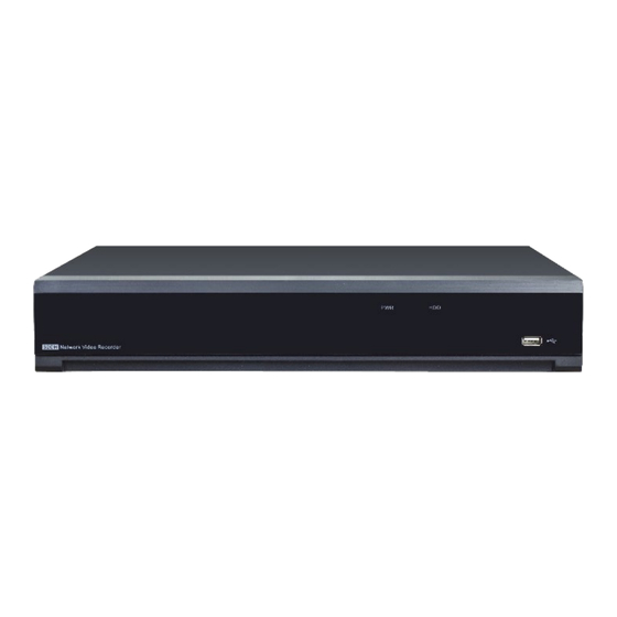
DESCRIPTION OF THE PARTS FRONT PANEL NVR stands for Network Video Recorder Equipment. FRONT PANEL NVR REF. 1098/334-364. Writing or Number Symbol Function and description indicator Power indicator The green LED on means that the NVR is powered correctly. The red LED blinking means that the user is reading or writing on Hard disk the hard disk. -
Page 12: Front Panel Nvr Ref. 1098/368
FRONT PANEL NVR REF. 1098/368. 2 3 4 5 Number Item Status Description Steady on The device is operating properly Power status indicator Not lit The device is shut down or not powered on Steady on The device is connected to the network properly LAN interface status indicator Not lit... -
Page 13: Rear Panel
REAR PANEL REAR PANEL NVR REF. 1098/334 Number Physical port Connection method Power switch Power on and off Power connector Power connector Sensor/Alarm interface Alarm or for alarm device connector USB 2.0 port 2 USB device connector, e.g. USB mouse HDMI ports High-definition HDMI ports Audio input... -
Page 14: Rear Panel Nvr Ref. 1098/368
REAR PANEL NVR REF. 1098/368 1 15 2 3 9 10 Number Physical port Connection method Audio input Audio signal input, RCA interface Audio output Audio signal output, RCA interface RS232 port RS232 connection HDMI-1 Primary output interface of the device, supporting output with 8K resolution HDMI-2 Secondary output interface of the device, supporting output with 4K resolution HDMI-3... -
Page 15: Installation And Connection
INSTALLATION AND CONNECTION 3.1 HDD INSTALLATION Depending on the NVR you have purchased, the hard disk drive (HDD) may be included in the full package. If it is not pre- installed, follow the installation instructions on this user manual. Caution: Do NOT install or uninstall the HDD while the NVR is powered on. (1) Install the ejector lever of the hard disk. -
Page 16: Connection Diagram
CONNECTION DIAGRAM *Above connection diagram is for illustration purpose only. The interfaces in your actual product may vary with models. POWER SUPPLY CONNECTION Caution: Use the power supply attached or specified by the manufacturer only. Contact your local dealer if any problem with the power supply is found. -
Page 17: Operation With Mouse
OPERATION WITH MOUSE The mouse must be used to operate the system. A. Left Button Click to select menu options. During live viewing in split-screen view, double-click on a channel to view it in full-screen. Double-click the channel again to return to split-screen viewing. -
Page 18: Osd Nvr Menu Settings
OSD NVR MENU SETTINGS After having plugged in the NVR, the system will run the initialisation procedures during which the following image will appear: At the end of the boot-up, the NVR will switch to Live view. FIRST NVR LOGIN The first time the NVR is switched on, the password must be set immediately to safeguard your privacy. -
Page 19: Reset Password
Click on Apply to confirm your settings and go back to the login interface. Enter your username and password to Login the NVR system. NOTE: If you forget your password, you can reset it via the hole (RESET) located at the rear of the NVR. Pressing it should last 10 seconds after which there is an audible warning (3 beeps) and the device restarts. -
Page 20: Reset With Super Code
Reset with Super Code 4.1.1.2 If you had activated the Super Code in Password Generation, you are able to reset your password with super code. Click the Forgot Password button on the login window. Choose Super Code. Provide the date and MAC address information to the authorized dealer. Input the Super code you get from the authorized dealer, and then input new password. -
Page 21: Live View Interface And Pop-Up Menu
LIVE VIEW INTERFACE AND POP-UP MENU DEFINITIONS OF ON-SCREEN ICONS AND MESSAGES Status Icons Icon Meaning The camera is being recorded currently A motion alarm is happening An intelligent or Ai alarm is happening The external I/O alarm device is being triggered The PIR alarm is being triggered HDD Error Icons Icon... -
Page 22: Camera Quick Toolbar
Channel Abnormal Message Meaning Message No camera is added to this channel. You can click the add icon to add a No Camera new camera. The added camera is off-lined or lost connection. Please check the camera Failed to connect to camera, please working status or network connection. -
Page 23: Taskbar
If your camera has white light LEDs, click this button to turn on or turn off the LEDs. If your camera has a built-in speaker, click this button to turn on or turn off the alarm sound. If your camera has warning light LEDs, click this button to turn on or turn off the LEDs. Tag button. -
Page 24: Shutdown / Reboot / Lock Screen Menu
Icon Meaning Fan status is normal (only for 1098/368) Fan status is abnormal (only for 1098/368) : Network is disconnected (available in the next firmware version). : Network is connected but offline (available in the next firmware version). : Network is well connected (available in the next firmware version). The device is in arming status. -
Page 25: Ptz Control
Afterwards, edit the Password in order to re-login to system press Unlock button for login again. Pressing the Pattern button will allow access to the main menu via the unlocking pattern if it was set during the first access. Note: Administrator has full authority over Main Menu operations and has an authority to limit common user’s operation. -
Page 26: Cruise Set
Icon Description Channel Click to select the channel of the PTZ AHD/IP Camera. Mode Click to select PTZ Pointer panel Click to start/stop the PTZ camera Click the up/down/left/right arrows to set PTZ camera navigation Speed Adjust PTZ speed Zoom Click to zoom in/out. -
Page 27: Tag Setup
TAG SETUP Move mouse to any a live channel, then right-click to view tools bar. The Add Customized Tag icon is Click on to view then click on . Set the Tag once, the Tag can record one minute, this is the default setting. Tag name may be edited, for example: Warning: User can select [General], [Sub-periods] and [Smart] options on the [Search] page and set the Tag event record. -
Page 28: To Search For A Tag Record Event
TO SEARCH FOR A TAG RECORD EVENT Click on Start Menu Setup Search Tag on the Tag event search page, then set Start Time, End Time, and Channel. Click on to view the list of event tags. DS1098-056... -
Page 29: Fisheye Camera
Playback: Click on to play the Tag recording event. Edit: Click on to modify the Tag name. Delete: Click on to delete the Tag recording event. FISHEYE CAMERA After a fisheye camera is added to the device and the device goes online, the fisheye operation icon is displayed in the shortcut menu of the preview channel area and the playback menu. -
Page 30: Alarm Notification Panel
ALARM NOTIFICATION PANEL ④ ① ② The Alarm Notification Panel displays thumbnails of alarm events that have occurred. Events are color- coded according to the event type. Use the mouse scroll wheel to scroll up and down (place the mouse cursor over the notification panel first). Click the play button next to or over the thumbnail to play the event. - Page 31 IP Address: The IP address identifies the NVR in the network. It consists of four groups of numbers between 0 to 255, separated by periods. For example, "192.168.001.100". Subnet Mask: Subnet mask is a network parameter which defines a range of IP addresses that can be used in a network. If IP address is like a street where you live then subnet mask is like a neighborhood.
-
Page 32: Date/Time
DATE/TIME This menu allows you to configure the Date, Time, Date Format, Time Format, Time Zone, NTP and DST. Date/Time Click on the calendar icon to set the current system date. Date: Click on the calendar icon to set the system date. Time: Edit the system time. -
Page 33: Ip Camera
IP CAMERA Add IP cameras to the NVR in this section. Connect IP camera to NVR PoE Ports 4.3.3.1 IP cameras will get online automatically if the IP cameras are connected to the PoE ports on the rear panel. The online cameras will be displayed on the right side of the window. -
Page 34: Add Ip Camera To Poe Nvr From Internet
2. Click the Search button on the left bottom corner of the window, all available cameras in the LAN will be displayed. Select the camera you want to add, then click the add icon Or click the Add icon in the channel list and then click Search button, all available cameras in the LAN will be displayed. Click on the camera you want to add. -
Page 35: Add Ip Camera To Non-Poe Nvr
Manual and click OK to save. 2. Click the Add icon in the channel list. 3. Input the IP camera's internet IP address, port, protocol, user name and password. Click Add button to complete. Add IP camera to Non-PoE NVR 4.3.3.4 For Non-PoE NVR, you need to add the IP cameras from LAN and/or Internet manually. -
Page 36: Disk
DISK HDD must be formatted If it is installed in the NVR for the first time. Select the HDD and then click Format HDD button to format the HDD. Overwrite: This instructs your NVR to overwrite the oldest video files as the hard drive becomes full. You also have the option of selecting the amount of days for recordings to be kept before they are overwritten. -
Page 37: 4.4 Main Menu
Tick "Don't show the Wizard after start." if you don't want to display the Start Wizard after the system start. Click Finish button to save & exit. 4.4 MAIN MENU All the NVR functions can be accessed from the Main Menu. If you have not logged in (main menu locked mode), you will need to enter Username and Password as shown in the following figure: For System Login press Unlock button. -
Page 38: Channel
Motion Thermal CHANNEL In this section, you are able to manage the camera connection, live view display, camera's image, PTZ setup, video cover, motion setup, and more. IP Channels 4.5.1.1 The IP cameras are configured by selecting IP Channels on the side menu. Click on [Search] to search IP cameras from local network. - Page 39 Click on the icon, a message will pop-up to tell the failure reason. If the failure reason is "User name or password error", it means the camera user name and password is different from the default user name and password. Click the edit icon and then change to its correct user name and password.
-
Page 40: Steps To Connect Plug & Play Poe Cameras (Solo Per Modelli Di Nvr Provvisti Di Porte Poe)
Import IPC from File: Click this button to import IP camera information. It allows you to add IP cameras in batches to a specified channel by importing a CSV file stored on an external storage device. If IP cameras have been added to the channel, after IP camera information is imported, the newly imported IP camera information will overwrite the old information. -
Page 41: Add Individual Camera In The Lan
If you want to add an individual channel manually, click the edit icon in the channel list, and then click the drop-down arrow next to Switch Mode to select "Manual" and click OK to save. Add individual camera in the LAN 4.5.1.4 Change the PoE mode to be Manual. -
Page 42: Add Multiplex Cameras In The Lan
Alias: To define the camera ID title you want to display in the live view screen. Port: Camera communication port. Protocol: To select the connection protocol. Bind channel: To determine which channel you want to add the camera. Click Add button. The added camera will be displayed in the channel list. -
Page 43: Add Cameras From Other Nvr In The Lan
The added cameras will be displayed in the channel list. Add cameras from other NVR in the LAN 4.5.1.6 The NVR allows to add cameras from other NVRs in the local network. Click Search button, all available devices in the LAN will be displayed. There is an edit icon displayed if the device is an NVR. -
Page 44: Add Cameras From Internet
The added cameras will be displayed in the channel list. Add cameras from Internet 4.5.1.7 If your NVR is connected to internet, you're able to add cameras from internet with WAN IP address. Click Add button in the search page. Input the IP address or domain name, port, protocol, user name &... - Page 45 Confirm to quit at this point. Now, the IP camera detected using the protocol employing the RTSP port can be added to the live grid of the NVR. Batch IP modification Select a camera group in the search list to customise its parameters (IP type, IP address, mask, gateway, user name and password).
- Page 46 It is possible to select the PoE channel priority between manually added camera or PoE camera. If Remember My Option is not selected, the option is only valid once. In case you need to reset the NVR (reset default) because you forgot the access password, you can recover the cameras in the following way: 1-Access the Channel menu screen ...
- Page 47 3- You can choose if you want to continue using the current camera password (the NVR can display the password for each camera) re-assign administrator password cameras. DS1098-056...
-
Page 48: Poe Power (Solo Per Modelli Di Nvr Provvisti Di Porte Poe)
PoE Power (solo per modelli di NVR provvisti di porte PoE) 4.5.1.8 In this page, you will find the real-time power consumption of each PoE port, total actual power & rated power. LIVE This page of the Display menu can be used to configure the parameters related to the <Live> screen of the NVR. As shown in the following figures, the available options may be different if an IP camera (figure on the right) is being configured. -
Page 49: Image Control
Here are the details related to other functions: Select a channel to be configured. Attribute a name to the camera. Date format to be displayed for the camera. Time format to be displayed for the camera. Monitor refresh rate (50 Hz or 60 Hz). This is used to view the name of the camera on the Live screen This is used to view the system time on the Live screen. - Page 50 Select a channel to be configured. Select the desired integrated IR cut filter mode to ensure the camera works correctly in D/N. Set the IR-CUT switching delay time. Set the infrared illuminator. Check to enable lens flip, angle flip and corridor mode. Set the flip angle.
-
Page 51: Full Color Camera Settings
Auto: In this mode, the white light is adjusted by the default parameters. Manual: In this mode, you can manually set the synthetic gained white light of red, green, and blue. Shutter: Used to set the shutter exposure time. There are two mode options. Auto: In this mode, a proper exposure time is automatically selected in accordance with the configured Time Exposure value. - Page 52 Schedule: you're able to set the white lights turned on or turned off in certain durations. Each square represents • 30 minutes. Using the mouse, click on a particular square to change or click and drag the mouse over the squares corresponding to your desired period.
-
Page 53: Ptz
This menu can be used to configure the PTZ (Pan-Tilt-Zoom) settings for the dome camera. To control PTZ cameras, click on PTZ (which stands for Pan Tilt and Zoom) to open the page shown in the following figure. On each channel, you can set the communication protocol, the speed and other information, as shown below: Channel: Channel name •... - Page 54 Step: To set the steps of each movement of the MFZ lens Zoom: To control the zoom in and zoom out: : Single click on the button, the lens will perform one movement to zoom out the image and auto focus. Click and hold ...
- Page 55 Speed: Adjust the speed control to alter how fast or slow the camera will pan or tilt. Move the slider to decrease or increase the speed. Controlling PTZ In this section, you're able to control the Pan/Tilt/Zoom and more. 1. Select PTZ mode. 2.
- Page 56 Auto focus. Load default values. All the parameters you set will be lost and restored to default values. Start or stop Watch Mode. If your PTZ camera supports auto tracking on the movement of human beings, you're able to control the tacking by ...
-
Page 57: Preset Position
Preset position 4.5.4.2 In this section, you're able to configure the preset positions. A preset position is a particular position within the image that you would like the camera to focus on. Up to 255 different preset positions can be created. Select PRESET mode. -
Page 58: Watch Mode
Watch mode 4.5.4.3 Watch mode allows the camera to perform a preset action when there is no any operation to the camera, such as moving to a preset position, starting cruise, etc. ① ② ③ ④ Select the Watch Mode. Set the time interval. -
Page 59: Line Scan
Pattern Scan: The camera will be implemented the Pattern Scan. Click button to start the Watch Mode. Press button to stop. Line Scan 4.5.4.4 Line Scan allows the camera to automatically cruise between position A to position B horizontally. Select Line Scan mode. Adjust the speed control to alter how fast or slow the camera will pan or tilt. -
Page 60: Pattern Scan
Click add button , a position box will be added and displayed in the position list. Click the box to choose a preset position. Maximum 32 positions can be added to a track. Click on the blank area on the right side of the position box, and then delete the preset position by clicking the delete button , or click button to change its sequence. -
Page 61: Video Cover Settings (Privacy Zone)
VIDEO COVER SETTINGS (PRIVACY ZONE) This menu allows you to create privacy zones if you want to partially cover some certain part of the image. You can create up to four privacy zones in any size and location on the camera image. Enable the Privacy Zone, and select how many zones you need. -
Page 62: Motion
MOTION This menu allows you to configure motion detection parameters. When a movement is detected by one or more cameras, the NVR will alert you to a potential threat at your home. It does this by sending you an email alert with an attached image from the camera to use as a reference (if this option is enabled) and/or sending push notifications via the mobile app. - Page 63 Motion Alarm Settings Click the Alarm button to change options for alarm notifications and more. Buzzer: When motion is detected, you can enable the NVR's buzzer to alert you for a predetermined amount of time. Click the drop-down menu to select a time. Alarm Out: If your NVR or IP camera supports to connect external replay output devices, the system can send an alert message to the external alarm devices.
-
Page 64: Pir
(Slide to the right to view more options) FTP Picture Upload: Click the checkbox to copy snapshots to your ftp server when the detection is triggered. FTP Video Upload: Click the checkbox to copy videos to your ftp server when the detection is triggered. Picture to Cloud: Click the checkbox to copy snapshots to the cloud via Dropbox or Google Drive when the detection is triggered. - Page 65 Multiple areas can be created. Each cell or square can be enabled to detect PIR. The same action also applies when deleting an area. Movement outside of the detection areas won't be detected therefore will not trigger recordings or event notifications.
- Page 66 PIR Alarm Settings Click the Alarm button to change options for alarm notifications, alerts and more. Buzzer: When PIR alarm is detected, you can enable the NVR's buzzer to alert you for a predetermined amount of time. Click the drop-down menu to select a time. Alarm Out: If your NVR or IP camera supports to connect external replay output devices, the system can send an alert message to the external alarm devices.
-
Page 67: Roi
Post Recording: This option instructs your NVR to record for a set time after an event has occurred. Show Message: When the detection is triggered, the alarm icon will appear on screen. Send Email: An email alert will be sent when alarm event is detected. Tick the checkbox if you want to disable this. (Slide to the right to view more options) FTP Picture Upload: Click the checkbox to copy snapshots to your ftp server when the detection is triggered. - Page 68 Define an application channel for the function. Select Setup to define the zone. Hold down the left mouse button and drag an ROI zone. Stream Type: You can define the type of video stream to be saved for the ROI zone. Region ID: A maximum of 8 ROI zones can be set per channel.
-
Page 69: Thermal
THERMAL IMPORTANT: Use this menu only in case of third-party thermal cameras specially integrated via ONVIF protocol. This menu doesn’t refer to Urmet Thermal camera models that the NVR connects to using the Private protocol. Select Thermal in the side menu to setup a thermal camera. Under Alarm in the bottom right-hand corner, it is possible to set the type of action to be performed upon a thermal alarm (buzzer/alarm output/alarm time/recording/etc.). -
Page 70: Record Settings
RECORD SETTINGS This subsection describes the configuration of the recording options made available by the NVR. From here, you can access and change the recording frame rate & resolution and recording schedule for each camera connected. You can also enable and set a schedule for your NVR to take a snapshot each time when an event occurs: Encode ... -
Page 71: Record
Record Settings This parameter defines the number of frames per second that will be recorded by the NVR. • Video Encode Type: For IP camera only. The NVR supports H.264, H.265 H.264+ and H.265+. • Bitrate Control: This selects the bitrate level. For a simple scene (e.g. a grey wall), a constant bitrate (CBR) is suitable. •... -
Page 72: Record Schedule
Stream Mode: By default, your NVR will record both Mainstream and Substream video (known as Dual-stream). • Mainstream (high quality) video is used for playback when using your NVR directly, and Substream (reduced quality) is used for remote playback on your mobile device. If remote playback is not required, you can select Mainstream recording only to save your storage space. -
Page 73: Capture
CAPTURE This subsection of the Parameters menu can be used to configure the parameters dedicated to the acquisition of images in alarm conditions and to the programming of the time slots during which the function must be active. Capture 4.6.3.1 The Capture item is used to configure the parameters for recording images in an alarm condition;... -
Page 74: Alarm Configuration
Channel: This can be used to select the channel to set the recording parameters. • Normal: A green time slot indicates that normal recording is set for the channel for the time slot • Motion: A yellow time slot indicates that the channel records only when a motion is detected during the time slot. •... -
Page 75: Pir Notification
Latch time: This can be used to set the external sensor alarm time when motion is detected (10sec, 20sec, 40sec, • 1min). Record: This can be used to select the channels to be recorded following the alarm detected by the NVR from the •... - Page 76 Buzzer: This can be used to set whether and how long to enable the buzzer in case of PIR detection (Disable, • 10sec, 20sec, 40sec, 1min). Alarm Out: This can be used to match the correct external alarm sensor number. •...
- Page 77 Show the IP channel • : :configure monitor area for PIR • You can set an area for motion detection PIR function by clicking on: • Copy: This can be used to copy current channel parameters to any other channel or to all channels. •...
-
Page 78: I/O Alarm Settings
I/O ALARM SETTINGS On this page, it is possible to configure alarm notification from an input of the NVR's I/O interface. Alarm In: Displays the NVR's alarm input number. Local: Alarm input devices connected to NVR CHx<- 1: Alarm input devices connected to IP camera. Alarm Type: Set the input type between NC (Normally Closed), NO (Normally Open) and OFF (Off). -
Page 79: Thermal
Default: Click "Default" to revert to default settings. • Copy: Use the "Copy" function to apply all settings to the other connected cameras. • Apply: Click "Apply" to save settings. • THERMAL Read the description under the following figures for this menu page: At this point, the alarms can be set according to the different states. -
Page 80: Combination Alarm
Alarm type Function The alarm trips when an object moves in the motion detection area. The sensitivity level can Motion/PIR be adjusted according to application needs. The system can convert the alarm signal emitted by the thermal imaging camera into a signal Thermal that can be identified by the system. -
Page 81: Ptz Linkage
Buzzer: This can be used to set whether and how long to enable the buzzer when a combination alarm event is • detected (Disable, 10sec, 20sec, 40sec, 1min). Alarm Out: If your NVR or IP camera supports to connect external replay output devices, the system can send an •... -
Page 82: Exception
Channel: This is used to select the channel to be set. • Switch: This is used to enable or disable the PTZ linkage function on and off • Alarm: Alarms selected in the window will activate the PTZ link function (if checked). •... -
Page 83: Alarm Schedule
Voice Prompts: This menu allows voice prompts to be set according to time periods: each alarm can support up • to 12 time periods. You can also choose the IP channels to which to associate the uploaded voice messages. ALARM SCHEDULE This function can be used to program the alarm notifications (Alarm out, Buzzer, Push, FTP Upload, Cloud Upload) for each channel. -
Page 84: Voice Prompts
VOICE PROMPTS It is possible to upload a customised alarm voice message. The system will automatically or manually play the audio associated with the intrusion event at the scene. File Management 4.7.9.1 Press on Mode to choose the mode for importing the audio file. There are three modes to choose from: Import Files: import a file locally (supports MP3, WMA and WAV audio formats). -
Page 85: Loop Management
Local: Local transmission. When this transmission mode is chosen, the audio output is connected to the side of the device. IPC: transmission from network camera. Choosing this transmission mode requires that the camera supports the voice transmission function and has an audio output. It is possible to set voice messages according to time periods: each alarm can support up to 12 time periods. -
Page 86: Deterrence
Local: Local transmission. When this transmission mode is chosen, the audio output is connected to the side of the device. IPC: transmission from network camera. Choosing this transmission mode requires that the camera supports the voice transmission function and has an audio output. Select the play device. - Page 87 Channel: Select the camera you wish to configure. Light Switch: Press to enable light signalling. Light Level: The light intensity can be set. Light Duration: The duration of the light signal can be set. Color Image: Only active for cameras with warm lights. Deterrence mode: It is possible to choose between Light warning and Light strobe.
-
Page 88: Siren
By default, the white lights will not trigger between and 04:30 p.m. and 06:30 a.m., however you can change this according to your needs. Each square represents 30 minutes. Using the mouse, click on a particular square to change or click and drag the mouse over the squares corresponding to your desired period. -
Page 89: Disarming
DISARMING After the one-click disarming function is enabled, you can cancel the response of the device to various alarms. On this page you can set the relevant parameters including the disarming switch, channel, type, and schedule. Note: the system Exception alarms are not controlled by one-click disarming. Disarming: Press to enable the function. -
Page 90: Setup
This section can be used to set up intelligent analysis, i.e. systems which generate descriptions of what is happening in the video stream. Artificial Intelligence (AI) is an advanced function for the system to detect varies of alarm events based on face detection, human detection and vehicle detection technology with AI powered IP cameras and take actions accordingly. - Page 91 Channel: Select the channel you want to configure. • IVA Lines: Enable or disable the IVA Lines. • Snap Mode: select how snapshots containing a recognized face will be captured. This can affect the number of facial recognition notifications that you will receive. This can be used to select Real Time mode / Optimal mode / Interval mode: o Realtime Mode: the camera tracks and captures the face of someone entering and leaving the facial detection area.
- Page 92 If you choose Line mode, you need to adjust the position, length of the line, and choose the detection direction from BA or AB. Detection Range: This can be used to customize the screen area. • 1. Enable detection in IVA Lines. 2.
-
Page 93: 4.8.1.2 Pd & Vd Pedestrian & Vehicle Detection
4.8.1.2 PD & VD Pedestrian & Vehicle Detection This section describes the configurations for vehicle and person recognition. IMPORTANT NOTE: The AI menu is preset for detection of people and vehicles but the function are available for second generation AI ... - Page 94 To enable detection in Rule Switch. 1. Select a Rule Type, only Normal available for this detection. 2. Click on four points in the camera picture to draw a virtual line. The sharpness of the area must be a convex polygon. The concave polygon will not be able to save the information.
-
Page 95: Pid Perimeter Intrusion Detection
PID Perimeter Intrusion Detection 4.8.1.3 This function detects people, vehicles or other objects entering and lingering in a predefined virtual area; when the alarm is triggered, certain actions can be taken. Channel: select the channel to be configured • Switch: enable or disable the PID function. •... - Page 96 BA: The NVR will only detect action from side B to side A; A B: The NVR will detect action from both side B to side A and side A to side B. Using the mouse, click on 4 points on the camera image to draw a virtual area. The area must be in the shape of a convex polygon.
-
Page 97: Lcd Line Crossing Detection
LCD Line Crossing Detection 4.8.1.4 This function detects people, vehicles or other objects crossing a predefined virtual line; when the alarm is triggered, certain actions can be taken. Channel: select the channel to be configured • Switch: enable or disable the LCD function. •... -
Page 98: Cc Cross Counting
Using the mouse, click on 4 points on the camera image to draw a virtual line. Click on Save to save the settings. To change the position or length of the line, click on the red box: the line will turn red. Hold down the left mouse button to move the line or drag its ends to change the length or position of the line. - Page 99 Select the type of object that you want to detect in Detection Target. Choose a Rule Number. This is the maximum number of lines that can be drawn. Maximum 4 lines. Enable detection in Rule Enable. Choose Rule Type. Using the mouse, click on 2 points on the camera image to draw a virtual line. From side A to side B, this is an input; from side B to side A, this is an output.
-
Page 100: Hm Heat Map
HM Heat Map 4.8.1.6 Heat Map is a video analytics tool to provide a graphic overlay in the form of a heat map displaying the area and frequency of motion detected. This is especially useful for retail businesses to track customer movement to better understand consumer behavior. -
Page 101: Cd Crowd Density Detection
CD Crowd Density Detection 4.8.1.7 This menu allows you to set the rules for detecting crowding in a specific area. Crowd density detection is based on face detection technology, which is used to detect crowd gathering to maintain a controllable order in certain area. When the total number of detected people in a certain area exceeds the pre-set allowed number, the system will send an alert. -
Page 102: Qd Queue Length Detection
Rule Number: Select the rule number representing the number of crowd detection areas. The CD function can only set one area. Rule Enable: Enables or disables the rule. Visible Area: Decide whether or not to display the crowd detection area. Remove: Press on the detection area box and press Remove to delete the area. -
Page 103: Lpd License Plate Detection
Max Detection: The NVR will generate an alarm if the number of people queuing in the detection area exceeds the maximum number of people set. Max Pro Time: The NVR will generate an alarm if the queue stays longer than the set time. Detection Range: You can choose the full screen or you can customise the area. - Page 104 Channel: Choose the channel to be configured. IVA Lines: Allows you to enable or disable IVA lines. Snap Mode: There are three recognition modes, default mode, real-time mode, and interval mode. - Default Mode: When the vehicle's number plate enters the monitoring area, the camera will always detect. After the vehicle number plate has left the monitoring area, the best and clearest of the images captured during this time will be sent to the device.
-
Page 105: Rsd Rare Sound Detection
RSD Rare Sound Detection 4.8.1.10 This menu allows you to set which of the specific background noises the camera should detect. You can choose dog barking, a child crying and/or gunfire. Switch: Enables and disables the abnormal sound detection function. Setup: Press to draw the virtual area on the image. -
Page 106: Sod Stationary Object Detection
SOD Stationary Object Detection 4.8.1.11 This function detects objects left or lost within a predefined area (e.g. luggage, bags, hazardous materials, etc.); when the alarm is triggered, certain actions can be taken. - Channel: select the channel to be configured - Switch: enable or disable the SOD function - Sensitivity: the sensitivity level is between 1 and 4 (default value: 2). -
Page 107: Sound Detection
- Using the mouse, click on 4 points on the camera image to draw a virtual area. The area must be in the shape of a convex polygon. It will not be possible to save a concave polygon. - Click on Save to save the settings. - To change the size of the area, click on the red box inside it: the borders of the area will turn red. -
Page 108: Video Tampering
- Deterrence Schedule: allows to configure the sound warning on an hourly basis. Each square represents 30 minutes. Using the mouse, click on a particular square to change or click and drag the mouse over the squares corresponding to your desired period. - Page 109 - Channel: Select the channel to be configured. - Switch: Enable or disable the function. - Sensitivity: The sensitivity is related to the percentage of the sensing object entering the area. The higher the sensitivity value for crossing the line, the easier it is to trigger an alarm. For example, if set at 100%, the alarm will be triggered as soon as the detection object touches the boundary of the set area.
-
Page 110: Region Entrance
Region Entrance 4.8.1.15 The intrusion detection function can detect if a target enters the area set in the preview and trigger an alarm accordingly. Available in cameras with firmware version 8.2.4 or higher. - Channel: Select the desired channel. - Switch: Enable or disable the function. - Sensitivity: The sensitivity is related to the percentage of the sensing object's input into the area. -
Page 111: Region Exiting
- Max pixel: The object must be smaller than the maximum pixel set in order to be recognised. - Detection Target: There are three types of objects that can be detected: Pedestrian: Only detects pedestrians. Motor Vehicle: Detects only motorised vehicles. Non-motorised Vehicle: Detects non-motorised vehicles only. - Page 112 Selecting Setup: - Channel: Select the desired channel. - Target Validity: Indicates the similarity between the object and the set detection type. The alarm is only activated when the set similarity is reached or exceeded. The higher the set level and the higher the similarity requirement, the more obvious the required object characteristics and the higher the accuracy of the alarm.
-
Page 113: Fire Detection (This Section Appears Only If A Thermal Camera Is Connected To The Nvr Via Private Protocol)
Fire Detection (this section appears only if a thermal camera is connected to the NVR via Private protocol) 4.8.1.17 This function allows to setup the sensitivity of the thermal camera to detect a fire. You have to enable the function and set the sensitivity value between 1 and 100, where 1 is less sensitive to fire detection. Temperature Measurement (this section appears only if a thermal camera is connected to the NVR via 4.8.1.18 Private protocol) - Page 114 Display Temperature Info On Stream: Displays temperature information on the stream. When enabled, the temperature measurement area and the monitored temperature are displayed in the thermal channel live view screen. Display Temperature Info On Optical Channel: Display temperature information on the optical channel. When enabled, the temperature measurement area and the monitored temperature are displayed simultaneously on the optical channel live view screen.
- Page 115 Area setting: In this second part of the menu, you can setup the rules (point, line or area) of measurement and others parameters. Set temperature measurement area: 1. Click Add to add temperature rules, the maximum number of temperature rules is 20. 2.
- Page 116 Alarm Rules: Alarm rules. There are the following alarm rules, including Above (Max.Temperature): The maximum temperature is greater than. Below (Max.Temperature): The maximum temperature is less than. Above (Min.Temperature): The minimum temperature is greater than. Below (Min.Temperature): The minimum temperature is less than. Above (Average.Temperature): The average temperature is greater than.
-
Page 117: Schedule
Schedule 4.8.1.19 This function allows the intelligent analysis functions for each individual channel to be programmed in time slots. To activate the desired intelligent function, the time schedule must be configured. The programme will be active 24 hours a day, 7 days a week. To set up the schedule, choose a channel, the intelligent analysis function and drag the slider to mark the time slots. - Page 118 Face Recognition Model: This indicates the Face Recognition model implemented on the device. • • FD Model: This indicates the Face Detection model implemented on the device. Enable Face Recognition: This can be used to enable Face Recognition on the device. •...
-
Page 119: Face Database Management
If the recognition model has been changed to a different version, the system would send you a notice, click "OK" to continue. If you click "Cancel", you would need to go to "Database Management" menu and then click "Update facial features"... - Page 120 - Backup Database: to make a backup of the database, save a file as *.db in the External Storage Device or USB Disk. - Group Name: Allow List/Block List/Stranger lists are defined in advance, you can click on the group name to change the name of the new group or add a new group.
- Page 121 - Edit: Click to configure into Import and Export configuration settings for Allow List or Block List: - Import: Click on Import to access the setup page. You can select Local Storage Device or External Storage Device DS1098-056...
- Page 122 Click on Local Storage Device to select a face image from the HDD Then select OK: External Storage Device: Or click on DS1098-056...
- Page 123 - Export: To export an image click on External Storage Device, select a face image from the HDD, then click OK: - Add Group: Click on , then select OK - Enable: The default setting is enable, if a group is not used it can then be disabled. DS1098-056...
-
Page 124: License Plate Management
License Plate Management 4.8.2.3 Allows you to set the list of number plates that are allowed and forbidden to drive through and also add customised groups. Enable: enables the desired LPD group. Group Name: Allows setting the name of the database group, Allow List , Block List and Stranger group . - Page 125 Press the Import button to manually enter the data for the individual number plate. Press the Export button to export the entire group data to an external drive. Press the Move To... button to check the plate data box and transfer it to another group. Press the Delete button to select the plate data box and delete it from the group.
-
Page 126: Alarm
ALARM FD Face Detection 4.8.3.1 Press on Alarm to setup the alarm parameters for the face detection function: • Channel: Each channel can be configured. Buzzer: To disable or enable the buzzer. An alarm tone will sound every 10, 20, 40 or 60 seconds when detection is •... -
Page 127: 4.8.3.2 Fr Face Recognition
4.8.3.2 FR Face Recognition To configure alarm actions for different groups when faces detected. Click on Alarm to define the parameters for face recognition alarms: Group Name: Select the group whose alarms you want to configure. • Enable Alarm: The default value is enabled. This does not need to be a group. If is not used it can be disabled. •... - Page 128 Local: External alarm devices connected to the NVR. CHx->1: External alarm devices connected to IP cameras. o Latch Time: This can be used to configure the alarm time in case of detection; possible values are 10 s, 20 s, 40 s, 60 s. o Save Face: Configure whether the snapshot of the recognized face will be saved to the face database on your NVR.
-
Page 129: Ad Attribute Detection
AD Attribute Detection 4.8.3.3 In this section, it is possible to configure possible actions related to the recognition of certain facial characteristics (e.g. presence or absence of a mask). Alarm Type: there are three types of alarm, close, no mask, with mask. Buzzer: allows the duration of the buzzer to be set in the event of an alarm. -
Page 130: Lpr License Plate Recognition
LPR License Plate Recognition 4.8.3.4 Once licence plates have been added to a group, alarm notifications can be set up. Group name: Group name. Enable Alarm: Enables or disables licence plate reading detection. Tick the checkbox of the group(s) you want to enable alarm function. If the checkbox isn't enabled, no actions specified for the group such as alarm notifications will be actioned by your NVR. - Page 131 Alarm: Press to access the alarm setting interface. Alarm Channel: Press to select the channels subject to alarm. Buzzer: allows the duration of the buzzer to be set in the event of an alarm. Alarm Out: if enabled, allows the alarm output to be switched after the alarm has been triggered. •...
-
Page 132: Pd & Vd Pedestrian & Vehicle Detection
PD & VD Pedestrian & Vehicle Detection 4.8.3.5 Click on Alarm to define the parameters for the alarms for human recognition and vehicle detection: Channel: Select the channel you want to configure • Buzzer: This can be used to disable or to active the buzzer to emit an alarm tone in 10, 20, 40 or 60 seconds when •... -
Page 133: Pid (Perimeter Intrusion Detection)
PID (Perimeter Intrusion Detection) 4.8.3.6 This menu allows the configuration of PID notifications. Channel: Channel name Buzzer: allows you to set the duration of the buzzer in the event of an alarm. Alarm Out: If enabled, allows the alarm output to be switched after the alarm has been triggered. Local: External alarm devices connected to the NVR. -
Page 134: Lcd (Line Crossing Detection)
LCD (Line Crossing Detection) 4.8.3.7 This menu allows the configuration of LCD notifications. Channel: Channel name Buzzer: allows you to set the duration of the buzzer in the event of an alarm. Alarm Out: If enabled, allows the alarm output to be switched after the alarm has been triggered. Local: External alarm devices connected to the NVR. -
Page 135: Cc (Cross Counting)
CC (Cross Counting) 4.8.3.8 This menu allows the configuration of CC notifications. Channel: Channel name Buzzer: allows you to set the duration of the buzzer in the event of an alarm. Alarm Out: If enabled, allows the alarm output to be switched after the alarm has been triggered. Local: External alarm devices connected to the NVR. -
Page 136: Cd (Crowd Density Detection)
CD (Crowd Density Detection) 4.8.3.9 This menu allows the configuration of CD notifications. Channel: Channel name Buzzer: allows you to set the duration of the buzzer in the event of an alarm. Alarm Out: If enabled, allows the alarm output to be switched after the alarm has been triggered. Local: External alarm devices connected to the NVR. -
Page 137: Qd (Queue Length Detection)
QD (Queue Length Detection) 4.8.3.10 This menu allows the configuration of QD notifications. Channel: Channel name Buzzer: allows you to set the duration of the buzzer in the event of an alarm. Alarm Out: If enabled, allows the alarm output to be switched after the alarm has been triggered. Local: External alarm devices connected to the NVR. -
Page 138: Lpd (License Plate Detection)
LPD (License Plate Detection) 4.8.3.11 This menu allows the configuration of LPD notifications. Channel: Channel name Buzzer: allows you to set the duration of the buzzer in the event of an alarm. Alarm Out: If enabled, allows the alarm output to be switched after the alarm has been triggered. •... -
Page 139: Rsd (Rare Sound Detection)
RSD (Rare Sound Detection) 4.8.3.12 This menu allows the configuration of RSD notifications. Channel: Channel name Buzzer: allows you to set the duration of the buzzer in the event of an alarm. Alarm Out: If enabled, allows the alarm output to be switched after the alarm has been triggered. •... -
Page 140: Sod Stationary Object Detection
SOD Stationary Object Detection 4.8.3.13 This menu allows you to configure the notifications of the SOD function. Channel: Channel name Buzzer: allows you to set the duration of the buzzer in the event of an alarm. Alarm Out: If enabled, allows the alarm output to be switched after the alarm has been triggered. Local: External alarm devices connected to the NVR. -
Page 141: Sound Detection
Sound Detection 4.8.3.14 This menu allows you to configure the notifications of the Sound Detection function. Channel: Channel name Buzzer: allows you to set the duration of the buzzer in the event of an alarm. Alarm Out: If enabled, allows the alarm output to be switched after the alarm has been triggered. •... -
Page 142: Video Tampering
Video Tampering 4.8.3.15 This menu allows you to configure the notifications of the Video Tampering function. Channel: Channel name Buzzer: allows you to set the duration of the buzzer in the event of an alarm. Alarm Out: If enabled, allows the alarm output to be switched after the alarm has been triggered. •... -
Page 143: Intrusion
Intrusion 4.8.3.16 This menu allows you to configure the notifications of intrusion function. Channel: Channel name Buzzer: allows you to set the duration of the buzzer in the event of an alarm. Alarm Out: If enabled, allows the alarm output to be switched after the alarm has been triggered. Local: External alarm devices connected to the NVR. -
Page 144: Region Entrance
Region Entrance 4.8.3.17 This menu allows you to configure the notifications of Region Entrance function. Channel: Channel name Buzzer: allows you to set the duration of the buzzer in the event of an alarm. Alarm Out: If enabled, allows the alarm output to be switched after the alarm has been triggered. Local: External alarm devices connected to the NVR. -
Page 145: Region Exiting
Region Exiting 4.8.3.18 This menu allows you to configure the notifications of Region Exiting function. Channel: Channel name Buzzer: allows you to set the duration of the buzzer in the event of an alarm. Alarm Out: If enabled, allows the alarm output to be switched after the alarm has been triggered. La Local: External alarm devices connected to the NVR. -
Page 146: Fire Detection (This Section Appears Only If A Thermal Camera Is Connected To The Nvr Via Private Protocol)
Fire Detection (this section appears only if a thermal camera is connected to the NVR via Private protocol) 4.8.3.19 Temperature Measurement (this section appears only if a thermal camera is connected to the NVR via 4.8.3.20 Private protocol) Set the thermal fire point detection or temperature measurement function, and the linkage actions to be executed after the alarm is triggered. - Page 147 Note: The camera needs to support IO output function, and the working time is controlled by the corresponding schedule. Record: You can choose if record that channel and others. Post Recording: You can set the duration of continuous recording after an event occurs. The options include 5s, 10s, 20s, and 30s.
-
Page 148: Statistics
STATISTICS In this submenu, statistics can be viewed and exported according to the chosen intelligent video analysis function. FR Face Recognition Statistics 4.8.4.1 Statistics for face recognition are implemented. our NVR can retrieve and present statistical data relating to the detection of faces when the Face Recognition is enabled on the camera. -
Page 149: Cc Cross Couting Statistics
press to show calendar, then you can select the date desidered. Press Export to save the data to a U disk. CC Cross Couting Statistics 4.8.4.3 People and vehicle counting statistics can be displayed on the basis of a specific time period and represented in diagram form. -
Page 150: Hm Statistics
HM Statistics 4.8.4.4 It is possible to display heat map statistics based on a specific time period and represented as a coloured map or graph. Your NVR can retrieve and present statistical data relating to the detection of objects when the Heat Map video analytic is enabled on the camera. -
Page 151: Ai Scenario
AI SCENARIO In this section you can set up intelligent analysis scenarios. CROSS COUNTING It is an AI application based on cross-counting functions that helps to control the attendance of customers/visitors/vehicles in public places such as restaurants, parks, zoos, theatres, museums and car parks. Channel 4.9.1.1 Enables real-time counting and display of results through a single camera. -
Page 152: Group
Group 4.9.1.2 Allows statistics and results to be displayed in real time per group. Mainly used for large venues with multiple camera- monitored entrances. Group: allows you to select the camera group whose information you wish to view. Live: Displays the preview screen and status of the channels appearing in the group. -
Page 153: Search
Configuring Map Information Press on to add the Map. Press on to set the camera position on the map. Press on to display full-screen map information and the current group's crossing statistics. Search 4.9.1.3 Allows you to search separately for statistical data by channel or group. Select the channel or group to search for, set the search duration by day, week, month or year and select the type of search (Person/Vehicle/Motion). -
Page 154: Setup
Setup 4.9.1.4 Allows you to set the configuration of the individual channel or desired camera group. Select Advertise Mode to set AD mode. Set the SEQ Dwell Time in seconds that refers to the time each image stays on the screen (default time set to 3 seconds). Press on Image to load advertising images from the USB device (supports up to 16 images in jpg, png and bmp format with a maximum resolution of 2560*1600). - Page 155 Return to camera or group viewing mode and press the full screen button in the top right-hand corner to display the image and live count data for the selected camera or group. Select Enable to enable the camera you wish to display on the channel page. If the camera supports AI functionality, the Setup and Alarm icons will be green, otherwise they will remain grey .
-
Page 156: Face Attendance
FACE ATTENDANCE This menu manages the attendance screen, which can record both attendance and results in real time. Name of the face presence interface (GUI Theme) Press up to access the face search interface (Face Attendance) in playback and select face images in the face group as default. - Page 157 Channels: Select the desired camera. Groups: select faces from the desired database. Press on to access the AI face database management interface. GUI Theme: Set the name that will be displayed on the face presence GUI. On Duty Time: Set the service start time. Off Duty Time: Set the service end time.
- Page 158 Mode: choose the mode for sending attendance results, day, week, month. Day: sends the attendance results of the previous day once a day. ♦ Week: Sends attendance results once a week. It is possible to choose the week of which to send the e-mail. For ♦...
-
Page 159: Object Classification
OBJECT CLASSIFICATION It is the real-time, full-screen display interface of face, person, motor vehicle and non-motor vehicle detection. Name of the vehicle and object statistics interface. Press on to access the people and vehicle search interface. Press on to access the configuration page. DS1098-056... - Page 160 GUI Theme: Name displayed on the interface. Statistics: The statistics time period can be set between 1, 2, 3, 4, 5, 6, 7 days, week, month and year. Channel: Select the channels whose statistics you want to view. Display the current date and time. Image of selected cameras in Select the number of windows to be displayed in the interface, 1, 2, 4 windows Real-time notification display button.
-
Page 161: 4.10 Network Configuration
4.10 NETWORK CONFIGURATION The Network section of the Parameters menu can be used to access all the NVR settings for accessing the Internet and the local area network (LAN), the email notification functions, the use of a DDNS (Dynamic DNS) etc. The submenu is: General Settings DDNS... - Page 162 Encryption: The security encryption protocol can be set. • • Internal PoE Interface: You can set the NVR in switch mode. If the IP camera is in a different network, this option allows you to connect them if the IP address, mask and gateway have been set. To enable the function you mast check the PoE DHCP Server box.
-
Page 163: Pppoe
PPPoE 4.10.1.2 This is an advanced protocol which allows the NVR to connect to the network more directly, via a DSL modem. Check the "Enable PPPOE" box, then enter the username and password for the PPPoE. Click on Apply; the system will reboot to activate the PPPoE setting. SNMP 4.10.1.3 (For future use) SNMP: Simple Network Manage Protocol, open source. -
Page 164: Port Configuration
Port Configuration 4.10.1.4 HTTP/HTTPS/RTSP Port: This is the port that will be used to connect remotely to the NVR (i.e., via the Web Client). • If the default port 80 is already used by other applications, you must change it. Client Port: This is the port that the NVR will use to send information. -
Page 165: Ddns Set
DDNS SET DDNS (or Dynamic DNS - see glossary for more information) is a service used to record a domain name and floating IP address with the DDNS server for the domain name to be routed towards the IP address even if it is modified in a dynamic IP system. -
Page 166: Email
A DDNS account can be requested free of charge from the websites www.3322.org, www.changeip.com or www.no-ip.com or a DDNS account can be requested for a charge on the website www.dyndns.org. You can register on the DDNS Service website to obtain a domain name, a user name and a password. The options to configure are: Server: Select the DDNS provider. -
Page 167: Email Schedule
Email: This can be used to enable or disable the configuration of the email parameters. • Encryption: This is used to specify whether communication with the email server is encrypted or not; the use of a • safety transfer protocol with data encryption makes it possible to encode the communicated information (including your email) to prevent monitoring of transmitted data or the password to hackers. -
Page 168: Ip Filter
Channel: This can be used to select the channel to be configured. • Motion: Use this option to define the time slots at which to enable sending in case of automatic motion detection. • • IO (I/O): Use this option to define the time slots at which to enable sending in case of sensor alarm detection. •... - Page 169 Block List: It includes a range of IP addresses you define that indicates what IP addresses are forbidden to access your NVR to prevent unauthorized IP addresses from logging into your NVR. Tick the checkbox of Enable to activate the IP filter function. Click on the ratio button of "Enable Block List".
-
Page 170: Voice Assistant (Beta Version)
Edit: Click on to change Start Address and End Address; you can set one or more addresses for Single Add. • Delete: Click on . The “Warning!” dialogue box will appear. Click on OK to delete the Address list. • Enable Blacklists: The Blacklist is disabled by default;... -
Page 171: Voice Assistant With Amazon Fire Tv Stick
Voice Assistant with Amazon Fire TV Stick 4.10.5.1 Input your Amazon account, and the click Bind button to connect to bind your Amazon account. To choose the video stream you want to cast to your TV monitor. Go to Channel – Live menu, and give a Channel Name which is easy to call to the channel(s) you want to cast to your TV monitor. - Page 172 To use your existing profile or add a new profile and login your Amazon account which is same as the one you bind to the HVR. Search cand install Amazon Alexa to your mobile phone from app store, and then login with the Amazon account which is same as the one you bind to the HVR.
- Page 173 Touch the search icon on the right top corner. Input the keyword: smart camera view, and search. DS1098-056...
- Page 174 Touch the “Smart Camera View” in the search result list. Touch “ENABLE TO USE”. You would need to link your Amazon account. Sign in the Amazon account which is same as the one you bind to the HVR. Touch “Done” after the skill is successfully linked. DS1098-056...
- Page 175 Touch “DISCOVER DEVICES” and wait a moment for the app to search the cameras. Touch Next when the devices were found and connected. Choose one of the devices and then touch SET UP DVICE. You can add the camera to a group or skip. DS1098-056...
- Page 176 Repeat the previous setup to add all cameras and then touch Done to finish. All added cameras will be listed in the Devices. Touch the Cameras icon to check all added cameras. DS1098-056...
- Page 177 Press and hold on the voice button on the remote controller of the fire TV stick, and speak the command clearly. The command could be like: Show the XXX camera / Show XXX. XXX is the camera channel name. For example, if the channel name is “Office”, you could speak “Show my office camera”.
- Page 178 Wait for a while, you will see the real time images from the Office camera in your TV monitor. If you want to quit the camera live view, speak “Stop”. If you have changed the channel name, you would need to discover and add the camera again. DS1098-056...
-
Page 179: Voice Assistant With Google Chromecast
Voice Assistant with Google Chromecast 4.10.5.2 Input your Google account, and the click Bind button to connect to bind your Google account. To choose the video stream you want to cast to your TV monitor. Go to Channel – Live menu, and give a Channel Name which is easy to call to the channel(s) you want to cast to your TV monitor. - Page 180 To login your Google account which is same as the one you bind to the HVR. Touch “Get Started” to create a home, and then touch “New devices”. Input the Home nickname and address and then touch “Next”. To allow location access for the app. DS1098-056...
- Page 181 The app will automatically try to search devices from your local network. Choose Chromecast / Google TV. Make sure your Chromecast is turned on already, then touch Next. Your Chromecast will be found. Touch Next to connect. Confirm the code by touching Yes. DS1098-056...
- Page 182 Choose a location for your Chromecast, then touch Next. Choose the Wi-Fi network for your Chromecast and input the Wi-Fi password to connect. Make sure the Wi-Fi you choose is the same one with your mobile phone and is in the same local network with your HVR. Touch Continue to next step. Touch No Thanks or Sign Up to login your google account.
- Page 183 Touch Next and Skip and finish the tutorial. Now the Chromecast has been added to your Google Home. Touch the + icon on the left top corner. Indoor, then choose Set up device. Choose “Work with Google”, touch the search icon on the right top corner and then input “smart camera view”. DS1098-056...
- Page 184 Touch on “Smart Camera View” in the search result. You would need to sign in your google account and allow the Google to access to your device. Wait for a while, the Smart Camera View application will be linked to the Google Home. DS1098-056...
- Page 185 Now the available cameras in your HVR will be displayed. Choose one of the cameras and then touch Next button. Choose a home & location for the cameras step by step. Repeat the previous step to add all cameras. DS1098-056...
- Page 186 Search and install Google Assistant app to your mobile phone from app store. Run the Google Assistant, login your google account which is same as the one you bind to the HVR. Now, you’re able to stream your camera to your TV monitor by using text or voice command, like “Show/play the *** Camera on XXX TV”, in which *** is the channel name of the camera, XXX is your TV’s name.
-
Page 187: Platform Access
PLATFORM ACCESS Onvif 4.10.6.1 This function is mainly used to connect third-party platforms, such as ECMS/NVMS, via the Onvif protocol. Enable:Check the box to enable the function. Authentication:Set the type of login authentication. The options are Digest_sha256, Digest, Digest/WSSE, WSSE. Choose one of these options to suit your third-party platform. -
Page 188: Event Push
live server address bar for the device, and enable and configure the code stream type and live broadcasting channels. After saving the configuration, you can go to the YouTube live room to refresh the page to watch live broadcasting. Enable: check the box to enable the RTMP live broadcasting function. Server Address: Enter the live broadcasting address and live code of the YouTube server. -
Page 189: Device
Push HTTP: Enable: enables or disables the event push function. Name: Sets the channel name. Push Way: Sets the push way. Select HTTP. Username: Set the username. Password: set the password. Server Address: set the server address. Port: Set the server port. (Port number range: 1-65535). URL: Set the server API. - Page 190 Videos, snapshots and log files will be kept on the hard drive. Select the relevant option, then click "OK". Input your password, then click "Authenticate". A message will appear noting the data that will be erased. Click "OK" to continue. The page with the list of main parameters can be accessed via this side menu item.
- Page 191 Click on in HDD Status to change Disk Type and Disk group: Hard Disk ID: This shows the HDD serial number. • Disk Type: This indicates the disk type. Possible values are: Read Write Disk, Redundant Disk, Read Only Disk •...
-
Page 192: Disk Group
name and password of NAS if you choose SMB/CIFS. • Server IP: IP the IP address of NAS storage. Directory Name: Input the directory name on which you want to save your recording data. • Disk Size: To set the capacity size of the NAS storage. •... -
Page 193: 4.11.1.3 S.m.a.r.t. (Self-Monitoring, Analysis And Reporting Technology) Information
Disk Group: Group to which to associate the HDD within the selected type. • • Record Channel: Here you can define which IP channels belong to the selected Disk Group. The "Select All" and "Invert Selection" buttons allow you to add all available channels to the group, or reverse the selection made, respectively. -
Page 194: Raid
RAID The RAID function has a high requirement on hard disk performance. To ensure long-term stable operation and reliability of RAID, it is recommended that you use enterprise-class hard disks (including brand, model, and capacity) for RAID creation and other configurations. If surveillance-class or desktop-class hard disks are used, data security may be affected. The company shall not be liable for the data loss or data damage caused thereby. - Page 195 Automatic RAID Creation Through one-click configuration, the device can quickly create RAID and virtual disks. RAID5 is created by default in one- click configuration, and at least four hard disks should be installed. Creating RAID Manually To create RAID manually, click Create RAID to open the Create RAID page. Set the RAID name, select the RAID type, select the hard disks, and click OK to create the RAID.
-
Page 196: Setting Hot Spare Disks
Setting Hot Spare Disks 4.11.2.3 To ensure RAID security, when RAID is in degraded status, the system can automatically carry out RAID rebuilding. Therefore, it is recommended that hot spare disks be configured. On the RAID configuration page, select an idle hard disk, click the Add HotDisk button, and confirm the hot spare disk setting. -
Page 197: Deleting Raid
Deleting RAID 4.11.2.5 Select the RAID to be deleted, click the Delete RAID button, enter the administrator password, and click OK to delete the RAID. Viewing RAID Information 4.11.2.6 Click the RAID Info button to open the RAID Info page to view the RAID function information. CLOUD The NVR can transfer the images and videos, captured by the cameras in case of alarm, to a Cloud storage service via Dropbox and Google Drive, a free service which allows you to easily store and share snapshots and have them always at... -
Page 198: Dropbox Settings
Dropbox settings 4.11.3.1 1. Before activation, we recommend that you create a Dropbox account first. Go to www.dropbox.com, input your name, email address, and password, agree to the terms & conditions, then click or tap the sign up button. If you already have a Dropbox account, you can skip this step. -
Page 199: Google Drive Settings
7. The Cloud has completed the setup if you find a new folder named by your NVR device name and MAC address in the Dropbox storage. Your alarm pictures and videos will be upload to this folder. Google Drive settings 4.11.3.2 1. - Page 200 Click Allow, the settings of your Google Drive cloud have completed now. DS1098-056...
-
Page 201: Ftp
The last available item in the Network section concerns the configuration parameters to access a FTP server on which to load the images and the recordings acquired following an alarm detected by the NVR. 4.11.4.1 FTP This menu can be used to enable the FTP function to view and upload snapshots captured by the NVR to the FTP storage device. -
Page 202: 4.11.4.2 Ftp Schedule
4.11.4.2 FTP Schedule This configuration page can be used, as seen in the other cases, to select on which times and days of the week the NVR must send the images/video to the FTP in case of a given event. Channel: This can be used to select the channel to be configured. -
Page 203: 4.12 System
4.12 SYSTEM This section allows you to configure the functional parameters of the system. To access it, press "System" at the top of the screen. The following subsections will appear in the menu below: General Settings Multi-User Settings Maintenance Settings IP Camera Maintain Information GENERAL... -
Page 204: Date And Time
Date and Time 4.12.1.2 Date and Time: The date and time can be set. Static: Check this box if you wish to enter the date and time manually. NTP: The NTP (Network Time Protocol) function allows the NVR to automatically synchronise its clock with a time reference server. -
Page 205: Output Configuration
o Start Time / End Time: Set the start time and end time of daylight saving time. Output Configuration 4.12.1.4 This menu can be used to configure the video output parameters. Video Output: Select the output options: • LIVE-OUT can be used to configure the main output parameters. Select LIVE-OUT from the Video Output drop-down menu. -
Page 206: Auxiliary Screen&Decoding
Scale: This can be used to adjust the size of the • screen displayed in scale. X Offset: This can be used to move the • displayed screen leftwards/rightwards. Y Offset (Y Offset): This can be used to move • the displayed screen upwards/downwards. -
Page 207: Privacy Statement
View mode: Allows you to set the number of squares in the output. Define SEQ Setting: allows you to define which channels and in which grid squares of the output to display them. Seq Mode: Select the number of video channels to be displayed in SEQ mode on the secondary screen. SEQ Dwell Time: Used to set the SEQ dwell time on the secondary screen in seconds. -
Page 208: Multi-User Settings
MULTI-USER SETTINGS This menu can be used to configure user name, password and user permissions. The system supports the following account types: ADMIN - System Administrator: The administrator has complete control of the system and can change • administrator and user(s) passwords and enable/exclude password protection. USER - Normal user: users can only access the live view, search, playback, etc. - Page 209 Unlock Pattern Enable: Enables the unlock pattern to access the NVR menu. Press to draw the unlock pattern. Number of Single User Logins: You can limit the simultaneous logins of multiple users by entering the maximum number of logins at the same time. Add New Users Select one of the currently disabled user accounts and click on the User Edit icon •...
-
Page 210: Maintenance Settings
Check the boxes next to the menus and system capabilities that the user can access. Click on All to check all • boxes. Click on Clear to not check any boxes. Click on Save to save the changes made. • MAINTENANCE SETTINGS In this section, you can search and view the system log, load the default settings, update the system, export/import system parameters and manage the automatic system reboot. -
Page 211: 4.12.3.2 Load Default
Log Searching and Backing Up: Click on the field by the side of Start Date & Start Time to select the starting date and time of the displayed • calendar search. Click on the field next to End Date & End Time to select the end date and time of the search from the displayed •... -
Page 212: Reset Button
Reset Button 4.12.3.3 Put flag on Format HDD, it is possible to erase the recording when the RESET button is pressed to reset to factory settings (Load Default). Upgrade 4.12.3.4 This function can be used you to update the NVR firmware. Copy the firmware file (.sw file) to the USB flash drive and insert it into the USB port of the NVR. -
Page 213: Parameter Management
Upgrade: When it is detected that the server has upgradeable firmware, this button is available. You can click it to confirm the upgrade operation on the device. Parameter Management 4.12.3.5 You can export land main menu settings on a USB flash drive, burn to a CD or import a configuration file exported from a USB flash drive to the NVR. -
Page 214: Developer Mode
Auto Reboot: Click to enable. • Time: You can set the day, week or month of the NVR reboot. • Developer Mode 4.12.3.7 This mode is only supported by some devices. This menu allows the log of the serial port to be saved on a USB stick. Recorder Debug: Select the location to save the logs. -
Page 215: 4.12.4.2 Load Default
Select the IP camera the firmware of which you want to update. • Click on the Select File button to select the file to be loaded on the USB flash drive, then click on OK. • Click on the IPC Upgrade button to start the upgrade. For authentication, you will need to enter the Administrator •... -
Page 216: Parameter Management
Select the IP camera to reboot and click on ; a message will prompt you to enter your password. • Enter the password and click on the “Authenticate” button to reboot the IPC. • Parameter Management 4.12.4.4 You can export land main menu settings on a USB flash drive or import a configuration file exported from a USB flash drive to the NVR. -
Page 217: Information
INFORMATION This menu can be used to view system information, channel information, logging information and network status. Information 4.12.5.1 This menu can be used to view system information, such as device ID, device model name, IP address, MAC address, firmware version and more. If the NVR supports P2P function, the P2P ID and QR code will appear on the information page. -
Page 218: Channel Information
Channel Information 4.12.5.2 This can be used to view channel information for each connected camera, such as pseudonym, mainstream and substream recording specifications, motion detection status and privacy mask. Record Info 4.12.5.3 This can be used to view the recording information for each connected camera, such as bitrate, flow type, recording resolution and frame rate (Fps). -
Page 219: Network State
Network State 4.12.5.4 This can be used to view the network information. 4.13 PLAYBACK & BACKUP The Search function can be used to search and play back previously recorded videos and snapshots stored on the NVR hard disk. You can select to play back videos that match the recording program, manual recordings or motion events only. The Backup function allows you to save important events (both video and snapshots) to a USB flash drive. - Page 220 Search Type: The system offers various types to restrict the search. Channel Selection: Select the channels to search and play. Video Playback Controls: To control the video playback. Enlarge video playback full screen Rewind, x2, x4, x8 and x16 (clicking repeatedly on the button) Slow motion playback, 1/2, 1/4 and 1/8 speed, 1/16 speed (by repeatedly clicking the button) Play Pause...
-
Page 221: Search & Play Video In General
SEARCH & PLAY VIDEO IN GENERAL This menu can be used to search and play back recordings based on the selected date. Select a date from the calendar to search for video recordings. 2. Select a search type. 3. Check the channels to be searched or check Channel to search for all connected channels. 4. - Page 222 The backup drive menu appears. Go to the folder where you want to save the backup files. 10. Click on OK to start. The progress bar on the bottom of the window shows the status of backup operation. DS1098-056...
-
Page 223: Event Search, Playback & Backup
EVENT SEARCH, PLAYBACK & BACKUP The event search can be used to view a list of video recordings, with the channel, start/end time and type of recording appropriately summarized. You can also quickly save events to a USB flash drive. Search, playback and backup of events: Select the date and time to search. -
Page 224: Event Playback Control
Detailed view: This can be used to view the details of the events. In the latter mode, you can block video events so that they are not overwritten on the hard disk. Click on the icon to block events or on the to unblock them. -
Page 225: Sub-Periods Playback
3. Control playback using the Video Playback Controls buttons. Click on the or right-click to exit playback and go back to the event search window. 4. The event being played will now be displayed on the timeline. 5. Use the Timeframe options ( ) to display a shorter or longer period. -
Page 226: Smart
SMART Sub-period playback allows you to play back multiple normal and motion event recordings from a single channel simultaneously. With normal and event recordings, the video is split evenly, depending on the split-screen mode selected. For example, if the video lasts one hour and split-screens x 4 mode has been selected, each split-screen will play for 15 minutes. -
Page 227: Tag
For more information, see section “Tag Setup” EXTERNAL FILE This function can be used to search and play back external files on a USB flash drive or USB DVD Writer. PICTURE SEARCH & VIEW This function can be used to search, play back and copy snapshots to a USB flash drive or USB DVD Writer. Search, playback and backup of images: Select the date and time to search. - Page 228 Check the types of images to be searched for or check Search Type to select all of them. Select the channels to search or check Channel to select all channels. Click on the button to start the search. The images which match the search criteria are displayed as a list. You can click on one of the images to enlarge Click on the icons at the bottom right of the menu to browse the image pages or to enter the page you wish to consult.
-
Page 229: Picture Preview Control
Picture Preview Control 4.13.8.1 Image list: The images can be selected here. Click on the button to save the selected images to a USB flash drive or CD/DVD media. Click on the button to see the images in a slideshow. Press the button to exit the preview control window and return to the image search window. -
Page 230: Slice
SLICE This function can be used to search, play back and copy video by choosing the video duration of the day of shooting, time of shooting. 1. Select the channel to search among the active ones, select the Month, Day, Year. 2. - Page 231 1. Select the channel to search among the active ones Select the Alarm Group lists (Group Name) among those defined on the system: Click on and select the Local Storage Device or External Storage Device. Click Local Storage Device to select a face image.
- Page 232 2. Area in which the videos which match the search and recognition criteria set are shown. 3. Playback area of the selected video. 4. Select one of the pictures in area 2 and select the search criteria in area 1 to obtain the videos of people with a face similar to the one set.
-
Page 233: License Plate
License Plate 4.13.10.2 In this section, video details can be viewed and exported once the number plate detection alarm has been activated and the event has been recorded. DS1098-056... - Page 234 Time: Set the time period for querying the number plate detection event. The date can be set by pressing License Plate: Filter and query based on licence plate information. Fault-Tolerant: Set the number of characters sufficient for licence plate detection. The value can be set from 0 to 5. Info Snapped: Details of the alarm event including the following data: - Channel: Channel selection - Start Time: start time of the event...
-
Page 235: Human & Vehicle Detection
Human & Vehicle Detection 4.13.10.3 In this section it is possible to search for information on persons and vehicles by setting the date, time, camera and type of detection desired. Press the left button to get basic information on the left side; press the right button to customise the playback and detail display. Press on the bottom left corner to play;... -
Page 236: Intrusion
Intrusion 4.13.10.5 In this section it is possible to search for information on people and vehicles that are present in a predefined area by setting the date, time, camera and type of object desired. Region Entrance 4.13.10.6 In this section you can search for information on people and vehicles that have entered a predefined area by setting the date, time, camera and type of object. -
Page 237: Region Exiting
Region Exiting 4.13.10.7 In this section it is possible to search for information on people and vehicles that have left a predefined area by setting the date, time, camera and type of object. Repeat Visitors 4.13.10.8 In this section it is possible to search and count the number of times the same face has been detected. Select the desired date and time. -
Page 238: Face Attendance
Check search results or press on All to select all search results. Press on the icon to customise playback or press to back up images and videos to the external USB drive. You can narrow your search by adjusting the "Min. Interval" time and the percentage of "Similarity". Min. - Page 239 Pressing on the result displays all survey data. Press on the icon to access the details interface. Here are the attendance details, including the first and last appearance. Press on to perform playback in the bottom left corner. Press on Export to save the record file of the searched attendance information to the U-disk. Press on Send Email to send the searched attendance information file to the mail address set in the device menu.
-
Page 240: Video Player To View Backup Videos On Pc
VIDEO PLAYER TO VIEW BACKUP VIDEOS ON PC This section allows you to play the backup files using to a powerful video player (to download from Urmet website). PC users must install the software "VideoPlayer_x.x.xx_xx_xx_xx.exe". Minimum system requirements: • Intel I3 or above •... -
Page 241: Video Player Control
VIDEO PLAYER CONTROL 1. Play List Add file Delete file Select the playback mode: play a single file and stop playback; play all listed files in sequence; repeat one file; repeat multiple files. Filter by file name 2. Hide/Show Play List Click to open the files or load a folder. - Page 242 Capture Settings: Set the format and save path of the snapshots. The Advanced Setup menu can be used to select the OSD language of the video player and configure its parameters. DS1098-056...
-
Page 243: Remote Access Via Web Client
REMOTE ACCESS VIA WEB CLIENT The Web Client can be used to remotely access the NVR via PC at any time. Before accessing the Web Client, ensure that the NVR Internet settings are configured correctly. BASIC SYSTEM ENVIRONMENT REQUIREMENTS The minimum hardware and OS requirements for the Web Client are as follows. Component Minimum Recommended... - Page 244 After the first login of the NVR from the Web interface, enter your custom Password and confirm. After installing the plug-in, close and launch the browser again, then repeat step 1 to open the login page. Enter your username and password to access the Web Client. DS1098-056...
-
Page 245: Web Client Manager
WEB CLIENT MANAGER The Web Client supports full control of the NVR with the administrator account. Protect your username and password against any illegal access. ACCESS TO THE NVR WEB INTERFACE VIA IP ADDRESS, URL OR URMET DDNS ACCOUNT Follow the instructions for configuring and accessing the web pages of the device on Edge in Internet Explorer mode. The web can be accessed in three ways: Direct access via LAN: start Edge in Internet Explorer mode and type the IP address and the HTTP port of the NVR on the address bar, as follows: http://IP Address: HTTP Port (e.g http://192.168.36.40:85). -
Page 246: Live Interface
LIVE INTERFACE This is the first screen that opens after the Web Client access procedure. Here you can open/close the live preview, manually record video on the local computer, take screen snapshots, perform PTZ control, adjust the colours, etc. Channel List: This can be used to open the channel list for the quick camera function. Click on to see the list of channels. - Page 247 AI Alarm • Color • PTZ Interface (Only for cetain models) Direction controls: press on the corresponding arrow to move the camera. Zoom: Click on -/+ to zoom in or out. Focus: Click on -/+ to adjust the focus. 3D position: cloick on to zoom one detail of the imagine AutoFocus: Click on autofocus to focus the camera automatically.
- Page 248 Line Scan page: Area scan: Click to record the start position and rotate the PTZ camera, and click to record the stop position. Speed: Select the linear cruise speed. Click to start linear cruise. In this mode, the PTZ camera moves on the same horizontal plane only.
- Page 249 Live display control buttons: To view the Layout page. To open the images in the Live window. To close all Live channels. Original Proportions: To show the Live video playing in its original proportions. Stretch: To stretch the Live video feed to fit the full area of each channel on the screen. To enlarge the Web Client full screen.
-
Page 250: Playback
PLAYBACK You can search and play back videos recorded and stored on the hard disk in the NVR and download them to your computer. To search the recordings: Click on Playback at the top right of the window. Select the search mode for video recordings or images, default is General: Select the day on which to search for recordings on the calendar. - Page 251 Choose the video stream you want to search and play. In case of playback of Substream recordings, check that you have set the NVR for recording with Dualstream, as shown in section "Record Settings" Select the type of recording to search for or select Normal Event - All and Intelligent - All to search for all recordings: Check the channels to search for recordings.
-
Page 252: Playback Control Buttons
PLAYBACK CONTROL BUTTONS Play the recordings Pause Stop Go Forward One Frame: Move one frame at a time through playback. Only available if Synchronous playback has not been checked. Click on one of the channels playing, then click the Record button to record the current video on your computer. Click again to stop recording. -
Page 253: Image Playback
Playback Speed: Click to select the playback speed. Play All Channels: Click to play all channels selected for the search. Only available if Synchronous playback has not been checked. Stop All Channels: Click to stop all channels. Only available if Synchronous playback has not been checked. Open/close the speaker and adjust the sound volume. -
Page 254: Smart Playback
SMART PLAYBACK After the motion detection function is enabled for the device, if there are motion detection alarms triggered, you can search the smart playback videos. Click to display the smart setting area. Click to select all areas. Click to clear all selected areas. PLAYBACK BY TAG On this page you can search all added tags, and edit, play back, or delete them as needed. -
Page 255: Ai Playback
AI PLAYBACK After the AI alarm function is enabled for the device, you can search AI alarm events on this page, including face detection, license plate detection, pedestrian and vehicle detection, PID&LCD, repeat customers, and face attendance events. CHANNEL CONFIGURATION 6.6.6.1 Channel and the respective sub-options: IP Channels and POE Power. - Page 256 POE Power: this page allows you to check the POE ports used and the power delivered to each port. 6.6.6.2 Live: the name, position, channel preview and the respective parameters can be modified. If the Show Time parameter is set to <disable>, the current time of the NVR system will not be shown in Live mode. DS1098-056...
- Page 257 6.6.6.3 Image Control (if supported by IP camera model): It is possible to set the parameters of the IP camera. 6.6.6.4 PTZ: allows the PTZ parameters of the camera to be set. This function is only supported for cameras with PTZ control.
- Page 258 6.6.6.5 Video Cover: Up to four privacy zones can be selected for each channel, as shown below. For detailed parameters, see the OSD Menu section of the NVR. To eliminate a privacy zone, select it and then click on the <Delete> button and then on <Save>.
- Page 259 6.6.6.7 Motion detection: This can be used to configure the sensitivity and set the area. The detailed parameters must be coherent with the local setting of the NVR. 6.6.6.8 PIR Detection: this can be used to configure the sensitivity and set the area for PIR detection. The detailed parameters must be coherent with the local setting of the NVR This function is only supported for PIR sensor cameras.
-
Page 260: Record
6.6.6.9 Thermal: The thermal function can be used to configure some actions to report abnormal behaviour detected by the Thermal camera. This function is only supported by Thermal Cameras. IMPORTANT: Use this menu only in case of third-party thermal cameras specially integrated via ONVIF protocol RECORD Click on the <Record>... - Page 261 6.6.7.2 Record Record: You can set Channel, Record, Stream mode and Pre-record. Schedule: recordings can be scheduled: green color indicates Normal record; yellow indicates Motion detection, blue indicates Thermal record and purple indicates PIR Detection. DS1098-056...
- Page 262 6.6.7.3 Capture: sub-menu Capture: you can automatically acquire images according to the program or set the parameters manually. Capture Schedule: recordings can be scheduled: green color indicates Normal record; yellow indicates Motion detection, blue indicates Thermal record and purple indicates PIR Detection. This section can be used to set up intelligent analysis, i.e.
- Page 263 Face Detection: The detection of faces of people moving within a predefined area. For a detailed description of the parameters refer to FD section of this manual. Pedestrian & Vehicle Detection: configurations for recognizing vehicles and people. For a detailed description of the parameters refer to PD & VD section of this manual. DS1098-056...
- Page 264 Perimeter Intrusion Detection: For a detailed description of the parameters refer to PID section of this manual. Line Crossing Detection: For a detailed description of the parameters refer to LCD section of this manual. DS1098-056...
- Page 265 Cross Counting: For a detailed description of the parameters refer to CC section of this manual. Heat Map: For a detailed description of the parameters refer to HM section of this manual. DS1098-056...
- Page 266 Crowd Density Detection: For a detailed description of the parameters refer to CD section of this manual. For a detailed description of the parameters refer to QD section of this manual. Queue Lenght Detection: DS1098-056...
- Page 267 License Plate Detection: For a detailed description of the parameters refer to LPD section of this manual. For a detailed description of the parameters refer to RSD section of this manual. Rare Sound Detection: DS1098-056...
- Page 268 Stationary Object Detection: For a detailed description of the parameters refer to SOD section of this manual. Sound Detection: For a detailed description of the parameters refer to the Sound Detection section of this manual. DS1098-056...
- Page 269 Video Tampering: For a detailed description of the parameters refer to the Video Tampering section of this manual. Intrusion: for a detailed description of the parameters, please refer to the Intrusion section of this manual. Region Entrance: for a detailed description of the parameters, please refer to the Region Entrace section of this manual. DS1098-056...
- Page 270 Region Exiting: for a detailed description of the parameters, please refer to the Region Exiting section of this manual. Fire Detection: for a detailed description of the parameters, please refer to the corresponding OSD menu section of this manual. Temperature measurement: for a detailed description of the parameters, please refer to the corresponding OSD menu section of this manual.
- Page 271 AI Schedule: allows the weekly programming of the functions. 6.6.8.2 Recognition Model Configuration: This section describes the features of the devices which are performing the intelligent analysis. For a detailed description of the parameters of this function, refer to Model section of this manual. Database Management: This section describes the features of the devices which are performing the intelligent analysis.
- Page 272 License Plate Management: This section describes the features of devices that perform licence plate reading. For a detailed description of the parameters of this functionality please refer to the License Plate Management section of this manual. 6.6.8.3 Alarm: This section defines the parameters for Alarms (Buzzer, Latch Time, Post Reconding etc.) for AI functions. For a detailed description of the parameters of this function, refer to Alarm section this manual.
- Page 273 License Plate Recognition: this section describes the possible actions related to the recognition of license plate. For a detailed description of the parameters of this function, refer to Alarm section of this manual. Pedestrian and Vehicle Detection: this section describes the possible actions related to human or vehicle recognition. For a detailed description of the parameters of this function, refer to Alarm section of this manual.
- Page 274 Cross Counting: this section describes the possible actions related to line crossing events. For a detailed description of the parameters of this function, refer to Alarm section of this manual. Crowd Density Detection: this section describes the possible actions related to crowd detection events. For a detailed description of the parameters of this function, refer to Alarm section of this manual.
- Page 275 License Plate Detection: this section describes the possible actions related to license plate detection events. For a detailed description of the parameters of this function, refer to Alarm section of this manual. Rare Sound Detection: this section describes the possible actions related to rare sound detection events. For a detailed description of the parameters of this function, refer to Alarm section of this manual.
- Page 276 Sound Detection: this section describes the possible actions related to sound detection events. For a detailed description of the parameters of this function, refer to Alarm section of this manual. Video Tampering: this section describes the possible actions related to video tampering events. For a detailed description of the parameters of this function, refer to Alarm section of this manual.
- Page 277 Region Entrance: this section describes the possible actions related to region entrance detection. Please refer to the Alarm section of this manual for a detailed description of the parameters of this functionality. Region Exiting: this section describes the possible actions related to region exiting detection. Please refer to the Alarm section of this manual for a detailed description of the parameters of this functionality.
- Page 278 Pedestrian & Vehicle Detection: this section describes the statistics related to human or vehicle recognition. For a detailed description of the parameters of this function, refer to Alarm section of this manual Cross Counting Statistics: this section describes the statistics related to line crossing events. For a detailed description of the parameters of this function, refer to Alarm section of this manual.
- Page 279 Heat Map Statistics: this section describes the statistics related to the heat map functionality. For a detailed description of the parameters of this function, refer to Alarm section of this manual. DS1098-056...
-
Page 280: Alarm Set (Allarme)
ALARM SET (ALLARME) The notifications can be set (e.g. Buzzer, Latch Time, Post Recording, Send Email, Show Message, Full Screen, FTP Picture/Video Upload, Cloud Picture/Video Upload, Record Channel) for events such as Motion, PIR, IO Alarm, Intelligent Analysis Events, PTZ Linkage, Exception, Alarm Schedule. The detailed parameters must be coherent with the local setting of the NVR. - Page 281 6.6.9.3 PIR 6.6.9.4 Intelligent 6.6.9.5 Thermal DS1098-056...
- Page 282 6.6.9.6 Combination Alarm 6.6.9.7 PTZ Linkage 6.6.9.8 Exception DS1098-056...
- Page 283 6.6.9.9 Alarm Schedule 6.6.9.10 Voice Prompts File Management DS1098-056...
- Page 284 Loop Management 6.6.9.11 Deterrence 6.6.9.12 Siren 6.6.9.13 Disarming DS1098-056...
-
Page 285: Network
NETWORK 6.6.10.1 General: users can assign the static IP and perform port-forwarding for the NVR according to the different routers. PPPoE: the user can enable the relevant network protocol by setting its parameters. This is an advanced protocol that allows the NVR to connect to the network more directly, via a DSL modem;... - Page 286 SNMP (SNMP): the user can enable the relevant network protocol by setting its parameters. Port Configuration: 6.6.10.2 DDNS (DDNS): After having the DDNS service (see below), it is possible to enable the <DDNS> function in any network type (Static, DHCP and PPPoE). At this point it is possible to access the NVR via the domain name (http://domain: port No).
- Page 287 6.6.10.3 EMAIL Email Configuration: enter the parameters of your e-mail account to which you will receive alarm notifications and other information. Please refer to your e-mail provider for the data to be entered. Email Schedule: you can plan on time slots and on the basis of the type of event detected to send the e-mail. DS1098-056...
- Page 288 6.6.10.4 HTTPS: is a security encryption protocol. You can choose between standard and customised. 6.6.10.5 IP Filter: the IP filter function can be set. The detailed parameters must be consistent with the NVR's local setting. DS1098-056...
- Page 289 6.6.10.6 Voice Assistant: the Amazon and Google voice assistant can be set up. Amazon Google DS1098-056...
- Page 290 6.6.10.7 Platform Access Onvif: this function is mainly used to connect third-party platforms, such as ECMS/NVMS, via the Onvif protocol. RTMP (Real Time Messaging Protocol): this function is mainly used to connect third-party platforms, such as ECMS/NVMS, via the RTMP protocol. Event Push Platform: this function allows you to set the protocol through which push event notifications are handled.
-
Page 291: Device
DEVICE Click on the <Storage> option to access its sub-options: Disk, Cloud and FTP. 6.6.11.1 Disk: This can be used to check HDD status, overwrite time and enable recording on the ESATA interface, as shown below. The detailed parameters must be coherent with the local setting of the NVR. DS1098-056... - Page 292 6.6.11.2 Cloud: This can be used to set the Cloud Storage parameters for your Dropbox and Google Drive account. The detailed parameters must be coherent with the local setting of the NVR. 6.6.11.3 FTP: This function is used together with the alarm function. The captured images or alarm recording can be uploaded to the FTP server via the network.
-
Page 293: System
FTP Schedule: it is possible to set up sending to the FTP server on time slots and on the basis of the event detected. SYSTEM Click on the <System> option to access its sub-options: General, Multi-Users, Maintenance, IP Camera Maintain and Information. - Page 294 Date and Time: you can choose to set the date and time in manual or synchronised mode. The NTP (Network Time Protocol) function allows the NVR to automatically synchronise its clock with a time reference server. This allows for always accurate time setting (the NVR will periodically synchronise automatically).
- Page 295 Output Configuration: this menu allows the video output parameters to be configured. Privacy Statement: this menu shows the privacy statement to personal data processing. DS1098-056...
- Page 296 6.6.12.2 Multi-users: This is used to configure username and password, as shown below. The detailed parameters must be coherent with the local setting of the NVR. 6.6.12.3 Maintenance: This can be used to set the Log, Load Default, Firmware Update, Import/Export Parameters and Auto Reboot functions of the NVR.
- Page 297 Load Default Reset Settings Upgrade DS1098-056...
- Page 298 Parameter Management Auto reboot Developer Mode DS1098-056...
- Page 299 6.6.12.4 IP Camera Maintain: This can be used to set the Firmware Update, Load Default, Auto Reboot and Import/Export parameters functions of the IP camera (Firmware update not available for IP camera with ONVIF protocol) The detailed parameters must be coherent with the local setting of the NVR. Upgrade Load Default DS1098-056...
- Page 300 IPC Reboot IPC Parameter Management DS1098-056...
- Page 301 Format IPC (Formatta IPC) 6.6.12.5 Information: This is used to check the device name, number and type, the MAC address, the software version, the IE version and the hardware version, as shown below. You can also read all channel information: Set Stream, Enable or Disable Status, Motion Supported, etc.
- Page 302 Channel Information Record Info Network Status DS1098-056...
-
Page 303: Local Setting
LOCAL SETTING Set the download destinations of the recordings and snapshots obtained through the Web Client and select the type of video file. Record Path: Click on to scroll through and select the folder where you want to save your manual video •... -
Page 304: Nvr Specifications Ref. 1098/334 (Pal Format)
NVR SPECIFICATIONS REF. 1098/334 (PAL FORMAT) Features Functions 1098/334 Compression format Video: H.265+, H.265, H.264+, H.264, MJPEG / Audio: G.711A /G.711U Video Inputs 32CH Video Outputs 2 CH Video Output HDMI (up to 4K) Audio Inputs/Outputs 1-CH Line In RCA / 1-CH RCA Audio Out 1024*768, 1280*720, 1280*1024, 1440*900, 1920*1080, 1600*1200, 1920*1200, Display Resolution / Frame Rate 3840*2160@25fps for single IP channel... -
Page 305: Nvr Specifications Ref. 1098/364 (Pal Format)
Weight ~ 3 kg IMPORTANT NOTES Product specifications may be subject to change without prior notice. About replacing/adding one or more HDD: the operations must be performed by qualified personnel or by contacting the closest technical centre. Contact the closest technical centre to see the complete list of compatible HDDs. ... -
Page 306: Nvr Specifications Ref. 1098/368 (Pal Format)
PTZ control RS485, IP protocol / AF lens control USB ports 1 x USB 2.0 on front panel / 2 x USB 3.0 on rear panel YES (for recording and backup) * eSATA port Ethernet 2 RJ45 1000 Base-T TCP/IP, DHCP, UDP, P2P, PPPOE, Private Cloud, Network protocols SMTP, HTTPS, PPPPoE, FTP, RTSP, UPNP, SNMP PoE ports... -
Page 307: 10 Maximun Recording Duration
*Face Detection (FD), *Cross Counting (CC), *Occlusion Detection, *Face recognition, *Human & Vehicle detection, *Heat Map, *Attribute Detection, *Face attendance, *Crowd Detection (CD), *Queue length Detection (QD), Rare Sound Detection (RSD), License Plate Detection (LPD), Fire Detection, Temperature Measurement Fish Eye Camera support 16-CH Inputs I/O Alarm 4-CH Output... -
Page 308: 11 Recording Alarm Setting
11 RECORDING ALARM SETTING Refer to the following table: “⊥” means “alarm only, no recording”; “AMR” means “alarm recording”; “NLR” means “normal recording”; “NOR” means “no recording”. The respective icon appears once the alarm has tripped; the following indications will appear in presence of multiple alarms. Recording modes Scheduled recording Recording alarm setting... -
Page 309: 13 Maintenance
Q: I cannot access the NVR Client. Why? A: Check that the network connection settings are correct and that the RJ-45 port contact is efficient. Check that the account and the password have been entered correctly. Q: I cannot find any recordings during playback. Why? A: Check that the HDD data line is connected correctly and that the system time is correctly set. - Page 310 DS1098-056 DS1098-056 Technical area URMET S.P.A. Customer Service 10154 TORINO (ITALY) +39 011.19.62.00.29 VIA BOLOGNA 188/C http://www.urmet.com Tel. +39 011.24.00.000 (AUTO) e-mail: info@urmet.com +39 011.24.00.300 - 323 MADE IN CHINA...
Need help?
Do you have a question about the PRO Series and is the answer not in the manual?
Questions and answers