Table of Contents
Advertisement
Quick Links
Advertisement
Table of Contents

Subscribe to Our Youtube Channel
Related Manuals for ADLINK Technology ETX-EV133


Summary of Contents for ADLINK Technology ETX-EV133
- Page 1 ETX-EV133 User’s Manual ver. 1.2...
- Page 2 Copyright 2004 ADLINK Technology Inc. All Rights Reserved. Manual Rev. 1.2 Nov 1, 2005 The information in this document is subject to change without prior notice in order to improve reliability, design, and function and does not represent a commitment on the part of the manufac- turer.
-
Page 3: Revision History
10/12/2004 - changed all reference to Audio Codec AL201A to VT1616 - added shared FDD support - updated SMB/I C parapgraph - added Appendix A : Heatspreader 11/1/2005 - changed I2C addresses for onboard devices ETX-EV133 User’s Manual Page 3... -
Page 4: Table Of Contents
System Management Bus (I2C) ........21 Page 4 ETX-EV133 User’s Manual... - Page 5 Heatspreader Dimensions ........47 ETX-EV133 User’s Manual...
- Page 6 Page 6 ETX-EV133 User’s Manual...
-
Page 7: Introduction
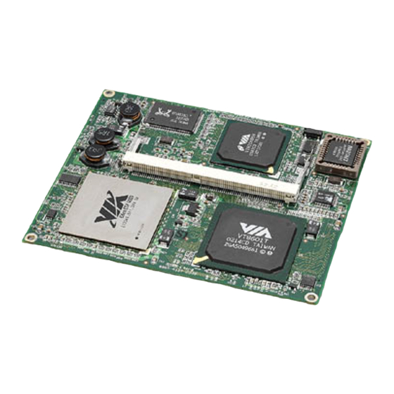
OEM customers to get to the market fast. ETX Core modules are also know as COM (Computer on module) or as SOM (System on Module). ETX-EV133 is based on the VIA’s Eden ESP processor combined with VIA Apollo PLE133T and VT82C686B chipsets. The onboard SODIMM socket supports 144-pin SODIMM type memory modules that can accommodates up to 512MB non-ECC SDRAM modules. -
Page 8: Specifications
FDD : one drive, (pinout shared with LPT1) IrDA : supports SIR IrDA 1.1 compliant USB : supports up to 4 ports ver 1.1 Keyboard & Mouse : one PS/2 keyboard and one PS/2 mouse Page 8 ETX-EV133 User’s Manual... -
Page 9: Audio
10 Watt typical ; (VIA Eden 600 MHz with 256 MB SDRAM) Operating Temperature : 0 to 55°C (32 to 140°F) Relative Humidity : up to 90% @ 55°C ETX Board Dimensions : 95 mm x 114 mm (3.7" x 4.5") Weight : 87 grams ETX-EV133 User’s Manual Page 9... -
Page 10: Function Diagram
VIA VT82C686B VIA VT82C686B ATA100 USB 1.1 Watchdog EEPROM Watchdog EEPROM Timer CMOS Audio Timer CMOS Backup Backup PCI to ISA Bridge Super I/O ISA bus ISA Bus Keyboard BIOS Mouse BIOS FDD/LPT1 COM1 COM2 Page 10 ETX-EV133 User’s Manual... -
Page 11: Mechanical Dimensions
4 Mechanical Dimensions ETX-EV133 User’s Manual Page 11... -
Page 12: Watchdog Timer
5 Watchdog Timer The ETX-EV133 includes a watchdog timer (WDT) that consists of a one-second resolution down counter. Once a value is written to the to WDT, the timer automatically starts to count down to 1 (not to zero !). -
Page 13: Connectors
- Keyboard 6.2 Pin-Out Compatibillity All pin-outs on X1, X2, X3 and X4 of the ETX-EV133 comply with pin-out and signal description used in the original : “ETX Specification ver 2.6”. This document includes : description of pin-outs, signal descriptions and mechanical characteristics of the ETX formfactor. -
Page 14: X1 Connector
AD12 LINEIN_R AD30 USB1+ AD13 AVCC PCIRST# AD31 AD14 LINEOUT_L INTC# INTD# AD15 AGND INTA# INTB# C/BE1# LINEOUT_R (1) pin 12, 16, 24 are for 3.3 V power output, with combined capacity of 500 mA Page 14 ETX-EV133 User’s Manual... -
Page 15: X2 Connector : Isa Bus
IOCHK# RSTDRV IRQ4 (1) IRQ12 is reserved for PS/2 mouse, this pin is NC on ETX-EV133 (2) DREQ2/DACK2# are signals to support an FDD controller on a secondary Super I/O chip, these pins are NC on ETX-EV133 ETX-EV133 User’s Manual... -
Page 16: Irda, Mouse, Keyboard
LCDDO6 RXD1 ACK# LCDDO1 LCDDO3 RTS1# BUSY# LCDDO0 LCDDO2 DTR1# DCD1# SLCT# JILI_DAT DSR1# MSCLK JILI_CLK BLON# CTS1# MSDAT BIASON PLPWR_EN TXD1 KBCLK TV_COMP TV_Y RI1# KBDAT TV_SYNC TV_C (1) These pins are not connected Page 16 ETX-EV133 User’s Manual... -
Page 17: X4 Connector : Ide1, Ide2, Ethernet, Miscellaneous
BATLOW# GPE1# RXD- PIDE_D8 SIDE_ACK# PIDE_INTRQ RXD+ SIDE_D7 SIORDY PIDE_ACK# TXD- PIDE_D7 SIDE_IOR# PIORDY TXD+ HDRST# (1) These pins are not connected (2) GPE1# for case open detection (3) GPE2# is for wake up system ETX-EV133 User’s Manual Page 17... -
Page 18: System Resources
The USB interrupt is internally routed to the PIRQD# input of the VT82C686B. This interrupt is routed to the IRQ14 input of the VT82C686B. This interrupt is routed to the IRQ15 input of the VT82C686B. Page 18 ETX-EV133 User’s Manual... -
Page 19: Pci Bus Arbitration Assignment
Bus area FFFEFFFF ~ FFFFFFFF Initialization area Direct Memory Access Channels DMA# Available Description Unavailable if Sound Blaster is enabled with default configuration Used by FDC Unavailable when LPT is in ECP mode Used for Cascade ETX-EV133 User’s Manual Page 19... -
Page 20: I/O Adddres Map
0CFC - 0CFF 4 bytes PCI configuration data 0D00 - FFFF Available for system use Notes: I/O space 370-371h is reserved for external I/O controllers . I/O space 3E8-3EFh is reserved for COM3, and 2E8-2EFh for COM4. Page 20 ETX-EV133 User’s Manual... -
Page 21: System Management Bus (I2C)
Adresses on the SMB/I C bus already occupied by devices on the module are : Address Function Device 1010 000 Identification Info SODIMM0 1010 111 CMOS setting backup EEPROM inside LAN ID Control and Status Ethernet # 1 ETX-EV133 User’s Manual Page 21... -
Page 22: Phoenix Award Bios
8.2 Main Menu Setup Items The main menu includes the following main setup categories. Recall that some systems may not include all entries. Standard CMOS Features (see paragraph 7.3) Use this menu for basic system configuration. Page 22 ETX-EV133 User’s Manual... - Page 23 Supervisor / User Password Use this menu to set User and Supervisor Passwords. Save & Exit Setup Save CMOS value changes to CMOS and exit setup. Exit Without Saving Abandon all CMOS value changes and exit setup. ETX-EV133 User’s Manual Page 23...
-
Page 24: Standard Cmos Features
Press the « or ( key to move to the desired field . Press the PgUp or PgDn key to increment the setting, or type the desired value into the field. IDE Primary and Secondary Master/Slave Items This selection brings you a configuration menu of the designated Drive (see next page) Page 24 ETX-EV133 User’s Manual... - Page 25 No errors : POST does not stop for any errors. All errors : If any non-fatal error, POST stops and prompts to take corrective action. All, But Keyboard : POST does not stop for a keyboard error, but stops for all other error ETX-EV133 User’s Manual Page 25...
- Page 26 Min = 0 Max = 65535 **** Warning: Setting a value of 65535 means no hard disk Landing zone Min = 0 Max = 65535 **** Sector Min = 0 Max = 255 Number of sectors per track Page 26 ETX-EV133 User’s Manual...
-
Page 27: Advanced Bios Features
These two categories speed up memory access. However, it depends on CPU/chipset design. Enabled : Enable cache, Disabled : Disable cache CPU L2 Cache ECC Checking This item allows you to enable/disable CPU L2 Cache ECC checking. Enabled, Disabled. ETX-EV133 User’s Manual Page 27... -
Page 28: Quick Power On Self Test
6, 8, 10, 12, 15, 20, 24, 30. Typematic Delay (Msec) Sets the delay time after the key is held down before it begins to repeat the keystroke. The choice: 250, 500, 750, 1000. Page 28 ETX-EV133 User’s Manual... -
Page 29: Security Option
Timeout in minutes to install agent if no serial connection can be established Agent after boot Enable this option to keep the Agent running after OS boot. Summary Screen Show Suppress the summary screen. Choice :Enable, Disable ETX-EV133 User’s Manual Page 29... -
Page 30: Advanced Chipset Features
However, some SDRAM cannot handle the lower cycle length and may become unstable. So, set the SDRAM Cycle Length to 2 for optimal performance if possible but increase it to 3 if your system becomes unstable. Page 30 ETX-EV133 User’s Manual... - Page 31 Select Enabled if your system contains a Universal Serial Bus (USB) controller and you have a USB keyboard. Choice: Enabled, Disabled. OnChip Sound This item allows you to control the onboard AC 97 audio. Choice: Enable, Disabled. ETX-EV133 User’s Manual Page 31...
- Page 32 Select Enabled to support compliance with PCI specification version 2.1. Choice: Enabled, Disabled PCI#2 Access #1 Retry When disabled, PCI#2 will not be disconnected until access finishes (default). When enabled, PCI#2 will be disconnected if max retries are attempted without success. Choice: Enabled, Disabled Page 32 ETX-EV133 User’s Manual...
-
Page 33: Integrated Peripherals
DMA driver. If your hard drive and your system software both support Ultra DMA, select Auto to enable BIOS support. Init Display First This item allows you to decide to active either PCI Slot or AGP first ETX-EV133 User’s Manual Page 33... - Page 34 Select an operating mode for the parallel port. Mode options are Normal, EPP, ECP, ECP/EPP. ECP Mode Use DMA Select a DMA channel if parallel Mode is set as ECP, ECP/EPP. Parallel Port EPP Type Select a EPP Type if parallel Port is set as EPP, ECP/EPP. Page 34 ETX-EV133 User’s Manual...
-
Page 35: Power Management Setup
Mode = 1 min., Standby Mode = 1 min., Suspend Mode = 1 min. User Defined Allows you to set each mode individually. When not disabled, each of the ranges are from 1 min. to 1 hr. HDD Power Down is always set independently ETX-EV133 User’s Manual Page 35... - Page 36 Blank Screen This option only writes blanks to the screen. DPMSInitial display power management signaling. Modem Use IRQ Name the interrupt request (IRQ) assigned to the modem (if any) on your system. Activity of the selected IRQ always awakens the system. Soft-Off By PWRBTN Page 36 ETX-EV133 User’s Manual...
- Page 37 Setting an event on each device listed to awaken the system from a soft off state. LPT & COM HDD & FDD PCI Master Power On by PCI Card Wake Up on LAN/Ring RTC Alarm Resume Date (of Month) Resume Time (hh:mm:ss) Primary INTR IRQs Activity Monitoring ETX-EV133 User’s Manual Page 37...
-
Page 38: Pnp/Pci Configurations
The Award Play and Play BIOS can automatically configure all the boot and Plug-and-Play compat- ible devices. If you select Auto, all the interrupt request (IRQ) and DMA assignment fields disap- pear, as the BIOS automatically assigns them. Page 38 ETX-EV133 User’s Manual... - Page 39 If this field set Enabled, any I/O access on the ISA bus to the VGA card's palette registers will be reflected on the PCI bus. This will allow overlay cards to adapt to the changing palette colors. ETX-EV133 User’s Manual Page 39...
-
Page 40: Pc Health Status
Displays the current System temperature Vcore, 2.5V, 3.3V, 5V Displays the actual voltage levels on the board Case Open Warning When enabled an audible signal is generated when pin GPE1# and CBLID_P# on X4 are disconnected. Page 40 ETX-EV133 User’s Manual... -
Page 41: Bios Post Codes
Program chipset default values into chipset. Chipset default values are MODBINable by OEM customers. Reserved Initial Early_Init_Onboard_Generator switch. Reserved Detect CPU information including brand, SMI type (Cyrix or Intel) and CPU level (586 or 686). ETX-EV133 User’s Manual Page 41... - Page 42 2. Put information on screen display, including Award title, CPU type, CPU speed …. Reserved Reserved Reserved Reserved Reserved Reset keyboard except Winbond 977 series Super I/O chips. Reserved Test DMA Channel 0 Reserved Test DMA Channel 1 Page 42 ETX-EV133 User’s Manual...
- Page 43 2. Early ISA PnP initialization 3. Assign CSN to every ISA PnP device. Reserved Initialize the combined Trend Anti-Virus code. Reserved Test EISA available memory Reserved 1. Initialize Init_Onboard_Super_IO switch. 2. Initialize Init_Onbaord_AUDIO switch. Reserved ETX-EV133 User’s Manual Page 43...
- Page 44 EPA or customization logo. Reserved Reserved 1. Call chipset power management hook. 2. Recover the text fond used by EPA logo (not for full screen logo) 3. If password is set, ask for password. Page 44 ETX-EV133 User’s Manual...
- Page 45 2. Update keyboard LED & typematic rate 1. Build MP table 2. Build & update ESCD 3. Set CMOS century to 20h or 19h 4. Load CMOS time into DOS timer tick 5. Build MSIRQ routing table. Boot attempt (INT 19h) ETX-EV133 User’s Manual Page 45...
-
Page 46: Appendix A : Heatspreader
In this way the heatsolution, that is built on top of the heatspreader is compatible with any kind of ETX module not just the ETX-EV133. It enables the second source model for ETX or upgrade path to a higher performance ETX module. Any change in ETX board type does not requirre the complete rebuild of the heat solution in your application. -
Page 47: Heatspreader Dimensions
A.1 Heatspreader Dimensions HTS-EV133 Aluminum Plate Heat Pad Thermal Aluminum Pad Paste ETX-EV133 User’s Manual Page 47...
Need help?
Do you have a question about the ETX-EV133 and is the answer not in the manual?
Questions and answers