
Related Manuals for Maiwe MIGE2210 Series


Summary of Contents for Maiwe MIGE2210 Series
- Page 1 MIGE2210 Series Gigabit Din-rail Switch User Manual Edition: V1.1) Wuhan Maiwe Communication Co., Ltd.
- Page 2 Copyright © Wuhan Maiwe Communication Co., Ltd. Clarification The user manual is applicable to MIGE2210 series gigabit din-rail switch. Please read the following license agreement carefully before using this manual. The products described in this manual can be used only if you agree on the following license agreement.
- Page 3 MIGE2210 Series Gigabit Din-rail Switch Safe Use Instruction This product performance is excellent and reliable in the designed range of use, but it’s necessary to avoid man-made damage or destroy for the equipment. Read the manual carefully and keep this manual for reference if need afterwards.
-
Page 4: Table Of Contents
MIGE2210 Series Gigabit Din-rail Switch Catalogue 1. Product Introduction..........- 1 - 1.1. Product Description..............- 1 - 1.2. Features..................- 1 - 1.2.1. High-performance Ethernet Switch Interface......... - 1 - 1.2.2. Industrial Power Supply Design............- 1 - 1.2.3. Shell Design..................- 1 - 1.2.4. -
Page 5: Product Introduction
MIGE2210 Series Gigabit Din-rail Switch 1. Product Introduction 1.1. Product Description The MIGE2210 series switches are high-performance unmanaged industrial Ethernet switches with 10 Ethernet interfaces. The product includes 2 Gigabit Ethernet interfaces and 8 100M Ethernet interfaces, which are suitable for applications with large bandwidth requirements. -
Page 6: Dual Power Backup And Power Failure Alarm
MIGE2210 Series Gigabit Din-rail Switch 1.2.4. Dual Power Backup and Power Failure Alarm MIGE2210 series products support dual power supply redundant input function The product has 1 relay alarm output function. When the switch is powered off, the relay is closed, and other sound and light alarm devices can be connected. - Page 7 AC85~264 1.5. Packing List The package of MIGE2210 series contains the following items. If any of the following items are lost or destroyed, please contact the agent or Wuhan Maiwe Communication Co., Ltd. Customer Service Center to assist you to replace or make up.
-
Page 8: Performance Indicators
MIGE2210 Series Gigabit Din-rail Switch 2. Performance Indicators System indicator MIGE2210 Series Industrial Ethernet Switches 2 Gigabit Ethernet ports + 8 100M Ethernet Number of ports ports Supported standards: IEEE802.3 (10Base-T), IEEE802.3u (100Base-TX), IEEE802.3x (flow System parameters control) MAC address table: 8K... - Page 9 MIGE2210 Series Gigabit Din-rail Switch load) MIGE2210-2GF: 2.4W@24VDC (no load); 3.8W@24VDC (full load) MIGE2210-2GF-4F: 2.3W@24VDC (no load); 4.5W@24VDC (full load) Over-current protection: built-in Housing: metal, no fan Physical size (length, width and height): Mechanical 144*110.4*54mm (excluding DIN rail assembly parameter...
-
Page 10: Hardware Structure
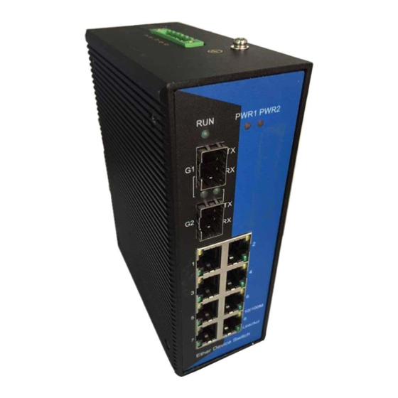
MIGE2210 Series Gigabit Din-rail Switch 3. Hardware Structure 3.1. Chassis The chassis of the MIGE2210 series industrial Ethernet switches is a small DIN rail structure. The whole machine adopts a six-sided fully enclosed structure. 3.2. MIGE2210-2GT Appearance The front panel of the MIGE2210-2GT integrates 2 10Base-T/100Base-TX/1000Base-T adaptive Tx ports and 8 10Base-T/100Base-TX adaptive Tx ports. -
Page 11: Mige2210-2Gf-4F Appearance
Figure 3-2 Front panel of the MIGE2210-2GF 3.5. LED Indicator Light The LED indicators on the front panel of the MIGE2210 Series Industrial Ethernet Switches show the status of the system operation and ports, making it easy to detect and resolve faults. The specific meaning is shown in the table 3-1 LED indicator status list. -
Page 12: Power Input Terminal
The port does not have a valid network connection 3.6. Power Input Terminal The schematic diagram of the power input terminals of MIGE2210 series switches is shown in the figure. As shown in Figure 3-4. Figure 3-4 Power supply input terminals of the MIGE2210 series switches... - Page 13 MIGE2210 Series Gigabit Din-rail Switch have two 1000Base-X full-duplex single-mode/multimode Fx interfaces, SFP hot-swap devices, and LC interfaces. The fiber interface needs to be used in pairs (TX and RX are a pair), the TX port is the optical transmitter, and the optical transceiver RX of the optical interface of another remote switch is connected;...
- Page 14 MIGE2210 Series Gigabit Din-rail Switch Attention This switch uses a laser to transmit signals over fiber optic cables. The laser meets the requirements of Class 1 laser products, and normal operation is harmless to the eyes. However, when powering up the unit, do not look directly at the optical transmission port and the fiber optic terminator end face.
-
Page 15: Hardware Installation
When you remove the device from the box, the DIN rail connector is fixed to the rear panel of the MIGE2210 series switch. If you need to mount the card on the DIN rail, you should check the DIN rail installation before installation. - Page 16 MIGE2210 Series Gigabit Din-rail Switch Connect power supply: The MIGE2210 series switch devices use the power supply as indicated on the product label. When all other cables are connected, you can connect to the power supply. - 12 -...
-
Page 17: Test Methods
MIGE2210 Series Gigabit Din-rail Switch 5. Test Methods 5.1. Self-test Process The power-on self-test phenomenon of the device under no load is: At the moment of power-on, all the 100 Mbps Tx port indicators on the front panel will flash once, and the two Gigabit Tx port indicators will only illuminate yellow before the RUN indicator starts flashing, and the two yellow lights will be off after the RUN indicator flashes. -
Page 18: Gigabit Fx Port Test
MIGE2210 Series Gigabit Din-rail Switch card works in the 10M state). The green light should flash. If you see the above phenomenon, it means that the two hundred megabytes of the tested hardware are working properly. Figure 5-2 Schematic diagram of the test connection of the 100M Tx port 5.4. -
Page 19: Network Connection
MIGE2210 Series Gigabit Din-rail Switch of the two MIGE2210-2GF-4S/M devices are connected by fiber cables. Each device is connected to a 100-Mbps Tx port through a direct-connected network cable and tested. The computers are connected, and the ping packets are sent to each other in the computer console, and both parties can correctly ping each other without losing packets. -
Page 20: Maintenance And Service
In order to ensure that consumers benefit from the series of products of Wuhan Maiwe Communication Co., Ltd., help and problem solving can be obtained by the following methods: Internet service Call the technical support office... - Page 21 WUHAN MAIWE COMMUNICATION CO.,LTD Add.:Building 2, Area E, Phase ii, Optical valley core center, No.52, Liufang road, East Lake Hi-tech Development Zone,Wuhan,China Phone: 027-87170215/16 Fax: +86-027-87170217 www.maiwe.com...
Need help?
Do you have a question about the MIGE2210 Series and is the answer not in the manual?
Questions and answers