Table of Contents
Advertisement
Quick Links
Advertisement
Table of Contents

Subscribe to Our Youtube Channel
Related Manuals for Insportline ProfiStair


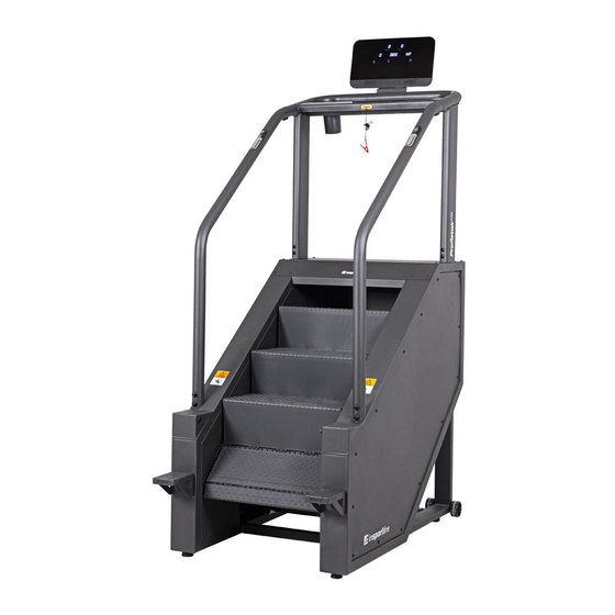
Summary of Contents for Insportline ProfiStair
- Page 1 USER MANUAL – EN IN 16385 Stepmill inSPORTline ProfiStair...
-
Page 2: Table Of Contents
CONTENTS OVERVIEW DRAWING ........................... 3 SAFETY PRECAUTIONS ........................3 POWER INPUT REQUIREMENTS ......................5 LEVELLING ............................. 5 POWER SWITCH ............................ 6 SAFETY KEY............................6 PARTS LIST ............................6 HARDWARE LIST ........................... 8 ASSEMBLY STEPS ..........................9 CONSOLE OPERATION INSTRUCTIONS ................... 15 HEART RATE EXERCISING ......................... -
Page 3: Overview Drawing
OVERVIEW DRAWING SAFETY PRECAUTIONS • Read this manual carefully before first use and retain it for future reference. • Use the product only according to this manual and for its intended purpose. Do not modify the product in any way. •... - Page 4 • Never use the stepmill if the plug or power cord are damaged. If the power cord doesn’t work properly or if it has been exposed to water, stop using it at once and have it repaired or replaced by a qualified technician or the customer service. •...
-
Page 5: Power Input Requirements
POWER INPUT REQUIREMENTS This product requires 220-240 V power and a well-grounded socket, as shown in the picture below. Make sure the power socket was installed by a qualified technician. Cables should be transported according to the corresponding laws of your country. High pressure cables, low pressure cables und underground cables should be transported separately and cannot be connected or tangled with other cables. -
Page 6: Power Switch
POWER SWITCH The power switch is located on the back of the stepmill (I=ON, O=OFF). SAFETY KEY The stepmill is equipped with an emergency stop system, including a safety key. Below are instructions on how to use the safety key in case of an emergency. •... - Page 7 G) Front upright tube set H) Rear upright tube set Support handlebar covers J) Rear upright tube covers K) Foot supports L) Waterproof covers N) Underside cover of the accessory tray...
-
Page 8: Hardware List
HARDWARE LIST STEP ITEM DESCRIPTION Hexagon socket head steel screw M10xP1.5x70 STEP 1 Flat washer ø10xø20x1.5t Hexagon socket head steel screw M10xP1.5x70 STEP 2 Flat washer ø10xø20x1.5t Umbrella head steel screw M8xP1.25x15 with nylon blue STEP 3 Flat washer ø8xø20x1.5t Hexagon socket head steel screw M8xP1.25x30 STEP 4 Hexagon socket head steel screw M8xP1.25x45... -
Page 9: Assembly Steps
ASSEMBLY STEPS STEP 1 – Main frame and the front upright tube set • First install the waterproof covers (L) onto both front upright tubes (G). • Then pull the main cable out of the upright opening on the right side of the Main frame (A) and pull the cable up through the right side Upright tube (G). - Page 10 STEP 2 – Main frame and the rear upright tube set • Attach the rear upright tube set (H) to the main frame (A) using screws (K03) and flat washers (K04). • Do not tighten the screws too much yet. STEP 3 –...
- Page 11 STEP 4 – Accessory tray and the support handlebar set • Look at the picture below. Attach the support handlebar (F) to the accessory tray set (E) with screws (K08) and camber washers (K09), but don’t tighten them too much. •...
- Page 12 STEP 5 – Main frame and the console set • Attach the console set (B) to the accessory tray set (E) and connect the control cables on the accessory tray (E) to the console cables. While connecting the cables, you will need one person to hold the console set so that it doesn’t fall down.
- Page 13 Console upper power cable Upper optical sensor cable Heart rate connection cable Middle control cable Console middle power cable Middle optical sensor cable Middle TV cable (optional only, depending on product type) Middle internet cable (optional only, depending on product type) Adobe connection wire...
- Page 14 STEP 6 – Support handlebar assembly • Look at the picture below. Use screws (K06) to secure the handlebar cover set (I) on the handlebar. • Use screws (K06 and K07) to secure the upright tube cover set (J) on the handlebar. •...
-
Page 15: Console Operation Instructions
STEP 8 – Level the stepmill • After finding the ideal position, turn the foot pads until they are lower than the transport wheels. CONSOLE OPERATION INSTRUCTIONS This stepmill features an easy-to-operate console for users of all ages. You can input your personal data to set your exercise goals more accurately. -
Page 16: Heart Rate Exercising
• Displays the resistance level profile while you’re exercising. Workout profile window • Height of the LED bar indicates the difficulty level. • Displays the current operation data of each program, Data such as calories, distance, time, inclination level and steps per minute (SPM). -
Page 17: Heart Rate Monitoring System
WARNING! Before you start exercising, you should consult your physician. Improper exercising can result in an injury or other health problems. You can ask a professional trainer for advice. High intensity: Interval Exercise Lower intensity: Burning Fats Select target heart rate as % of the max. value Available heart rate range: 55% - 90% HEART RATE MONITORING SYSTEM... -
Page 18: Exercise Programs
EXERCISE PROGRAMS There are the following preset programs: QUICK START When the stepmill is turned on, press QUICK START to begin exercising right away. To calculate the correct number of calories burned, input your weight and choose a suitable level. Press LEVEL+ and LEVEL- to adjust the speed. - Page 19 Heart rate control display image Corresponding target heart rate Take a 40-year old user as an example. The target heart rate is 80% of your maximum heart rate. You’ll find out your maximum heart rate by subtracting your age from 220: (220-40) x 80% = 144 Interval heart rate control –...
-
Page 20: Programs
Set the program to determine the target heart rate and choose the speed-up and slow-down speed. After a three-minute warm-up, the stepmill increases the speed to your set speed-up limit to help you achieve the 85% target heart rate. The speed will hold steady for a stabilizing period and then the system will slow down to return your heart rate to the 65%. -
Page 21: Speed Interval
The intensity of the exercise gradually rises as the stepmill speeds up to make your heart rate Warm-Up reach the minimum target. It quickens your breathing and stimulates blood circulation. Your goal at this stage is to maintain the heart Plateau rate at the minimum level. -
Page 22: Fat Burn
FAT BURN This low intensity exercise program is intended to burn the fat while maintaining the 65% target heart rate. It is necessary to wear the chest strap or to grasp the heart rate sensors in the handlebars. If the heart rate is not received well, a heart symbol will be displayed to warn you that the heart rate value comes from the hand heart rate sensors rather than the chest strap. -
Page 23: Trouble Shooting
TROUBLE SHOOTING Error code Possible reason Solution Note Power switch is OFF Turn the power switch ON. The power switch light is Check socket power Make sure off. output. voltage is 110/220V. Inverter didn’t power Console without Replace the inverter. power output 12V (DC) Control... -
Page 24: Switching Between Metric And Imperial Units
the inverter. inverter. voltage is 110/220V. Replace the inverter, the Inverter emergency shut control cables or the main down. board of the console. Apply lubrication oil, clean off Overheating warning for dust replace the inverter. inverter. Replace the inverter, control Inverter communication cables or the main board of... -
Page 25: Terms And Conditions Of Warranty, Warranty Claims
5) Press ENTER 4 times to go back to the standby page and to save the setting. TERMS AND CONDITIONS OF WARRANTY, WARRANTY CLAIMS General Conditions of Warranty and Definition of Terms All Warranty Conditions stated hereunder determine Warranty Coverage and Warranty Claim Procedure. - Page 26 Cermenska 486, 749 01 Vitkov, Czech Republic CRN: 26847264 VAT ID: CZ26847264 Phone: +420 556 300 970 E-mail: eshop@insportline.cz reklamace@insportline.cz servis@insportline.cz Web: www.insportline.cz INSPORTLINE s.r.o. Headquarters, Warranty & Service centre: Elektricna 6471, 911 01 Trencin, Slovakia CRN: 36311723 VAT ID: SK2020177082 Phone: +421(0)326 526 701...
- Page 27 E-mail: objednavky@insportline.sk reklamacie@insportline.sk servis@insportline.sk Web: www.insportline.sk Date of Sale: Stamp and Signature of Seller:...
Need help?
Do you have a question about the ProfiStair and is the answer not in the manual?
Questions and answers