Table of Contents
Advertisement
Quick Links
Advertisement
Table of Contents

Related Manuals for Insportline IN 5563


Summary of Contents for Insportline IN 5563
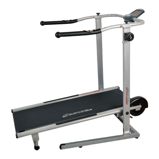
- Page 1 USER MANUAL - EN IN 5563 Magnetic Treadmill inSPORTline Jorney...
-
Page 2: Table Of Contents
CONTENT IMPORTANT SAFETY INSTRUCTIONS ......................3 OVERVIEW DRAWING ............................4 PARTS LIST ................................5 TOOL ..................................7 ASSEMBLY INSTRUCTIONS ..........................8 OPERATING THE COMPUTER ......................... 12 STORAGE ................................13 ADJUSTMENTS ..............................14 LUBRICATION..............................15 MAINTENANCE ..............................16 TROUBLESHOOTING ............................16 WARM UP AND COOL DOWN ROUTINE ...................... -
Page 3: Important Safety Instructions
IMPORTANT: Read all instructions carefully before using this product. Retain this owner’s manual for future reference. The specifications of this product may vary from this photo, subject to change without notice. IMPORTANT SAFETY INSTRUCTIONS Basic precautions should always be followed, including the following safety instructions when using this magnetic treadmill: Read all instructions before using this magnetic treadmill. -
Page 4: Overview Drawing
OVERVIEW DRAWING... -
Page 5: Parts List
PARTS LIST Description Main Frame Handlebar Support Frame Incline Adjuster Handlebar Support Frame Base Tube Handlebar Ø28x1.5t Front Roller Rear Roller Front Roller Axle Ø12x512 Rear Roller Axle Ø12x480 Magnet Bracket Magnet 30x15x8 Nut M6 Spring Ø23xØ1.6x110 Tension Control Knob Bracket 74x25x31 Bolt M5x10 Running Deck 444x1065x12... - Page 6 Hexagon Head Bolt M10x60 Big Washer Ø10xØ20 Bolt M8x15 Washer Ø8xØ16x1.5t Locking Knob M8x65 Handlebar Knob M8x45 Wire Grommet Ø12.1 Hand Pulse Sensor with Wire 1200mm Screw ST4.2x20 Handlebar End Cap Ø32 Handlebar Foam Grip Ø31xØ37x430 Cap Nut M8 Computer (HR1752) Bolt M8x50 Tension Control Knob Big Washer Ø5xØ20...
-
Page 7: Tool
End Cap 40x20x1.5 Locking Pin Ø8x38 End Cap 60x30x1.5 Bolt M8x40 Nylon Nut M8 Incline Adjuster End Cap Ø38x1.5 Washer Ø5xØ12x1.0 Extension Sensor Wire (L=750mm) Right Side Rail 990x20x1.5 Square End Cap (38x38x1.5) SILICONE OIL INCLUDED TOOL Allen Wrench Multi Hex Tool with Phillips Screwdriver S10, S13, S14, S15 1PC... -
Page 8: Assembly Instructions
ASSEMBLY INSTRUCTIONS Tool: Allen Wrench 6mm 28 29 Step 1 Place the magnetic treadmill in the upright position. Remove twelve M8x15 Bolts (28) and twelve Ø8xØ16x1.5t Washers (29) from both Handlebar Support Frame Base Tubes (4). Remove bolts with the 6mm Allen Wrench provided. Install both Handlebar Support Frame Base Tubes (4) to the Handlebar Support Frame (2) by inserting both Handlebar Support Frame Base Tubes (4) into the Handlebar Support Frame (2), using twelve M8x15 Bolts (28) and twelve Ø8xØ16x1.5t Washers (29) that were removed. - Page 9 Step 2 Place one hand on the rear end of Main Frame (1) and use the other hand to remove the Locking Knob (30) by turning it in a counterclockwise direction from the Handlebar Support Frame (2). Then Lower the Main Frame (1) down onto the floor and align Locking Knob hole.
- Page 10 Step 3 Remove two Handlebar Knobs (31) from the Handlebar Support Frame (2) and Handlebar (5). Then pull the Handlebar (5) all the way up. Install two Handlebar Knobs (31) onto the Handlebar (5) by turning them in a clockwise direction into the holes on the Handlebar (5) to secure the Handlebar (5) in place.
- Page 11 Tool: Multi Hex Tool with Phillips Screwdriver S10, S13, S14, S15 Step 4 Remove two ST4.2x20 Screws (34) from the back of the Computer (38). Remove screws with the Multi Hex Tool with Phillips Screwdriver provided. Remove the battery cover that is located on the back of the Computer (38). Connect the Hand Pulse Sensor Wires (33) and Extension Sensor Wire (58) to the wires that come from the Computer (38).
-
Page 12: Operating The Computer
OPERATING THE COMPUTER SPECIFICATIONS: TIME --------------------------------------------------- 0:00-99:59 MIN: SEC SPEED ------------------------------------------------ 0.0-99.9 KM/H DIST (DISTANCE) ---------------------------------- 0.00-99.99 KM CAL (CALORIES) ----------------------------------- 0.0-999.9 KCAL ODO (ODOMETER) -------------------------------- 0.0-999.9 KM PULSE ------------------------------------------------ 40-240 BEATS/MIN USING YOUR COMPUTER The computer can be activated by pressing the button or by receiving the signal from the speed sensor. -
Page 13: Storage
4. Replace the battery cover. 5. If the display is illegible or only partial segment appear, remove batteries and wait 15 seconds before reinstalling. STORAGE Handlebar Knob Handlebar Knob Locking Knob Locking Knob Figure 1 Figure 2 Remove the Locking Knob from the Handlebar Support Frame and Main Frame, see Figure 1. Lift the rear end of the Main Frame up in the vertical position and align Locking Knob hole. -
Page 14: Adjustments
ADJUSTMENTS Tension Control Knob Adjusting the Tension Control Knob To increase the load, turn the Tension Control Knob in a clockwise direction. To decrease the load, turn the Tension Control Knob in a counterclockwise direction. Locking Knob Adjusting the Incline Adjuster There are 3 incline angles that the incline adjuster can be set to. -
Page 15: Lubrication
If the running belt begins to shift to the left, the user can stand on the Main Frame and hold the handlebar with both hands. Then use your right foot to run on the right side of the running belt. You should see the running belt start to correct itself by moving back towards the center. -
Page 16: Maintenance
MAINTENANCE Cleaning The magnetic treadmill can be cleaned with a soft clean damp cloth. Do not use abrasives or solvents on plastic parts. Please wipe your perspiration off the magnetic treadmill after each use. Be careful not get excessive moisture on the computer display panel as this might cause an electrical hazard or electronics to fail. Please keep the magnetic treadmill, specially, the computer console, out of direct sunlight to prevent screen damage. - Page 17 feeling the stretch up the left side of your neck, then rotate your head back for one count, stretching your chin to the ceiling and letting your mouth open. Rotate your head to the left for one count, then drop your head to your chest for one count.
- Page 18 QUADRICEPS STRETCH With one hand against a wall for balance, reach behind you and pull your right foot up. Bring your heel as close to your buttocks as possible. Hold for 15 counts and repeat with left foot. INNER THIGH STRETCH Sit with the soles of your feet together and your knees pointing outward.
- Page 19 HAMSTRING STRETCHES Extend your right leg. Rest the sole of your left foot against your right inner thigh. Stretch toward your toe as far as possible. Hold for 15 counts. Relax and then repeat with left leg. CALF/ACHILLES STRETCH Lean against a wall with your left leg in front of the right and your arms forward. Keep your right leg straight and the left foot on the floor;...
Need help?
Do you have a question about the IN 5563 and is the answer not in the manual?
Questions and answers