Table of Contents
Advertisement
Quick Links
Advertisement
Table of Contents

Related Manuals for Insportline IN 13080


Summary of Contents for Insportline IN 13080
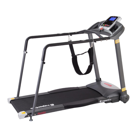
- Page 1 USER MANUAL – EN IN 13080 Motorized Treadmill inSPORTline Neblin...
-
Page 2: Table Of Contents
CONTENTS SAFETY INSTRUCTIONS ........................3 IMPORTANT ELECTRICAL INFORMATION ..................4 IMPORTANT OPERATION INSTRUCTIONS ..................4 ASSEMBLY INSTRUCTIONS ......................... 5 ASSEMBLY STEPS ..........................6 GROUNDING METHODS ........................9 OPERATION GUIDE ..........................10 WINDOW DISPLAY ........................... 10 BUTTON FUNCTIONS ........................11 EXERCISE INSTRUCTIONS ........................ 11 MAINTENANCE ............................ -
Page 3: Safety Instructions
Special tips: 1. Before installation and operation, please read this operation manual carefully. 2. Please save this manual for future reference. 3. Product may vary slightly from the item pictured due to model upgrades. SAFETY INSTRUCTIONS WARNING – Read all instructions before using this treadmill. It is important your treadmill receives regular maintenance, you can further its longevity this way. -
Page 4: Important Electrical Information
Remove the safety key after use to prevent unauthorized treadmill operation. IMPORTANT ELECTRICAL INFORMATION WARNING! 1) NEVER use a ground fault circuit interrupt (GFCI) wall outlet with this treadmill. Route the power cord away from any moving parts of the treadmill including the elevation mechanism and transport wheels. -
Page 5: Assembly Instructions
Warning: We suggest that you consult your physician or health professional before starting your workout, especially if you are over 35 years old or have a health problem. We take no responsibility for any troubles or hurts if you don’t follow our specification. The treadmill needs to be carefully assembled and the motor shield covered. -
Page 6: Assembly Steps
RIGHT FOOT PEDAL LEFT SIDE COVER BOLT M8*50 CONNECTING TUBE RIGHT LEFT HANDLEBAR RIGHT SUPPORT TUBE HOOK SPRING WASHER ARC WASHER LUBRICATION OIL Assembly tools: 5# Allen wrench 5 mm – 1pc Wrench with screw driver S=13, 14, 15 – 1pc Notice: Do not connect to the power supply before complete assembly. - Page 7 STEP 3: Use the 5# Allen wrench and M8*15 bolts (39) and lock washers (55) to lock the upright tubes onto the main frame. Notice: Support the upright tubes so that they don’t fall down. STEP 4: Use the 5# Allen wrench and M8*15 bolts (39) and lock washers (55) to lock the console (B) onto the left and right upright tube.
- Page 8 STEP 6: Fix the left & right side covers (33, 34) to the base frame with bolts M5*12 (75). STEP 7: Fix the connecting tube (1) to the console handle bar with bolts M8*50 (44), arc washers (49) and nuts (28). STEP 8: Connect the left handlebar (79) with the left support tube (81) and the right handlebar (80) with the right...
-
Page 9: Grounding Methods
STEP 9: 1. Connect the wires of hand pulse with speed (A), and hand pulse with start/stop (B) first. 2. Insert the hooks (84) on the handlebars (79, 80) first, then fix the left and right handlebar assembly to the console with triangle knob M6*10 (85). -
Page 10: Operation Guide
OPERATION GUIDE WINDOW DISPLAY SPEED: Displays the speed in the range of 0.3 - 6 km/h. TIME: Displays running time. In modes where a target time has not been specifically set, the display will count up from 0:00 to 99:59 minutes. -
Page 11: Button Functions
The heart rate frequency monitoring system isn’t always accurate. Overexertion of organism during training can lead to a serious injury or death. If you start to feel faint, stop the exercise immediately! BUTTON FUNCTIONS START: With the power switch on and the safety key in place in the console, press this button and the machine will start. -
Page 12: Maintenance
2. EXERCISE PHASE This is the stage where you put the effort in. After regular use, the muscles in your legs will become stronger. Work as you like but it is very important to maintain a steady tempo throughout. exertion should be sufficient to raise your heart beat into the target zone shown on the graph below. - Page 13 AFTER EACH USE (DAILY) Clean and inspect the treadmill according to these steps: 1) Turn off the treadmill with the on/off switch, then unplug the power cord at the wall outlet. 2) Wipe down the running belt, deck, motor cover, and console casing with a damp cloth. Never use solvents, as they can cause damage to the treadmill.
-
Page 14: Belt/Deck/Roller Lubrication
REPRESENTATIVE TO UNDERTAKE ONE OF THE STEPS ABOVE, PLEASE CALL OR EMAIL GENERAL CLEANING 1) Use a soft, damp cloth to wipe the edge of the belt and the area between the belt edge and the frame. A mild soap and water solution along with a nylon scrub brush will clean the top of the textured belt. -
Page 15: Tightening The Belt/Poly V-Belt
2) Spread the lubricant onto the inside surface of the belt and the deck evenly (make sure the machine is turned off and power is disconnected). 3) Periodically lubricate the front and rear rollers to keep them at their peak performance. If the treadmill belt/deck/roller is kept reasonably clean, you’ll further the treadmill’s longevity. - Page 16 PIC B PIC A Picture A If the belts has drifted to the RIGHT Picture B If the belt has drifted to the LEFT WARNING: ALWAYS UNPLUG THE TREADMILL FROM THE ELECTRICAL OUTLET BEFORE CLEANING OR SERVICING THE UNIT.
-
Page 17: Exploded Drawing
EXPLODED DRAWING... -
Page 18: Parts List
PARTS LIST DESCRIPTION SPECIFICATION QTY. Connecting tube Main Frame Computer Bracket Left Upright Right Upright Motor Bracket Left foot pedal Right foot pedal Front Roller Rear Roller Wrench w/ screw driver S=13, 14, 15 5# Allen Wrench 5 mm Adjustable wheel Console top cover Motor top cover Motor bottom cover... - Page 19 EVA cushion Bolt M8*35 Bolt M8*15 Bolt M8*20 Bolt M8*25 Bolt M8*38 Bolt M8*40 Bolt M8*50 Screw ST4.2*15 Bolt M6*55 Bolt M6*45 Bolt M6*35 Arc washer Screw M5*8 Screw ST4.2*12 Handlebar foam Washer Washer Washer Washer C Control board Inductor Optional Filter Optional...
-
Page 20: Trouble Shooting
Magnetic core Screw M5*12 Bolt M8*35 Screw ST4.2*12 Safety band Optional Left handle bar Right handle bar Left support tube Right support tube Safety band hook Optional Hook Triangle bolt M6*10 Handpulse with speed Handpulse with start/stop TROUBLE SHOOTING 1. There is no display on screen after the machine is connected to the power source: a. -
Page 21: Terms And Conditions Of Warranty, Warranty Claims
5. E05 display: Over load current protect a. If the the current is too strong, the system will automatically shut down to protect itself. Please restart the machine. b. It’s possible part of the machine is blocked and causing a problem with the moto. Please add the oil to the machine and restart. - Page 22 VAT ID: CZ26847264 Phone: +420 556 300 970 E-mail: eshop@insportline.cz reklamace@insportline.cz servis@insportline.cz Web: www.insportline.cz INSPORTLINE s.r.o. Headquarters, Warranty & Service centre: Elektricna 6471, 911 01 Trencin, Slovakia CRN: 36311723 VAT ID: SK2020177082 Phone: +421(0)326 526 701 E-mail: objednavky@insportline.sk reklamacie@insportline.sk servis@insportline.sk...
- Page 23 Web: www.insportline.sk Date of Sale: Stamp and Signature of Seller:...
Need help?
Do you have a question about the IN 13080 and is the answer not in the manual?
Questions and answers