Table of Contents
Advertisement
Quick Links
Operating manual
Portamess 911 Conductivity
Version TA-193.202-PMD01 130701
Software version: 1.x
Please carefully read these operating instructions before use. · Do not discard.
The operator shall be liable for any damage caused by installation or operating errors.
The latest version of the operating instructions are available on our homepage.
Part number 999609
Target group: instructed personnel
A3425
Version: BA DT 068 09/21 EN
EN
Advertisement
Table of Contents

Related Manuals for ProMinent Portamess 911 Conductivity


Summary of Contents for ProMinent Portamess 911 Conductivity
- Page 1 Operating manual Portamess 911 Conductivity A3425 Version TA-193.202-PMD01 130701 Software version: 1.x Please carefully read these operating instructions before use. · Do not discard. The operator shall be liable for any damage caused by installation or operating errors. The latest version of the operating instructions are available on our homepage.
- Page 2 Supplemental directives General non-discriminatory approach In order to make it easier to read, this docu‐ ment uses the male form in grammatical struc‐ tures but with an implied neutral sense. The document is always aimed equally at women, men and gender-neutral persons. We kindly ask readers for their understanding in this sim‐...
- Page 3 Supplemental directives Symbol Description ‘Display/GUI’ Screen elements (e.g. buttons, assignment of function keys). Presentation of software elements and/or texts. CODE...
-
Page 4: Table Of Contents
Table of contents Table of contents The Portamess 911 Conductivity.................... 5 Scope of delivery......................5 Brief description of the unit..................... 5 Safety............................6 Labelling of Warning Information..................6 User qualification......................8 General safety information..................... 9 Operation..........................10 Construction of the unit....................10 Display.......................... -
Page 5: The Portamess 911 Conductivity
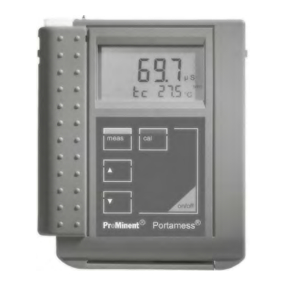
The Portamess 911 Conductivity The Portamess 911 Conductivity A3426 Fig. 1: The Portamess 911 Conductivity Scope of delivery The unit complies with the requirements of the EMC Act and the NAMUR NE 21 recommenda‐ Please check the completeness of the delivery tions. -
Page 6: Safety
Safety Safety Labelling of Warning Infor‐ mation WARNING! Introduction Nature and source of the danger These operating instructions provide informa‐ Possible consequence: Fatal or very tion on the technical data and functions of the serious injuries. product. These operating instructions provide Measure to be taken to avoid this detailed warning information and are provided danger. - Page 7 Safety NOTICE! Nature and source of the danger Damage to the product or its surround‐ ings. Measure to be taken to avoid this danger. – Denotes a possibly damaging sit‐ uation. If the situation is disre‐ garded, the product or an object in its vicinity could be damaged.
-
Page 8: User Qualification
Safety User qualification WARNING! Danger of injury with inadequately qualified personnel The operator of the system / equipment is responsible for ensuring that the qualifications are fulfilled. If inadequately qualified personnel work on the unit or loiter in the hazard zone of the unit, this could result in dangers that could cause serious injuries and material damage. -
Page 9: General Safety Information
Safety Training Definition Electrical technician An electrical technician is able to complete work on electrical systems and recognise and avoid possible dangers independently based on his technical training and experience as well as knowledge of pertinent standards and regulations. An electrical technician must be able to per‐ form the tasks assigned to him independently with the assistance of drawing documentation, parts lists, terminal and circuit diagrams. -
Page 10: Operation
Operation Operation Construction of the unit Ä Chapter 2.2 ‘User qualification’ on page 8 User qualification: instructed user meas on/off Portamess A2588 Fig. 2: Construction of the unit Sensor connector Reference electrode Temperature sensor connector not assigned Sensor quiver... -
Page 11: Display
Operation Display A2589 Fig. 3: Display Wait, sensor set-up time Zero point/gradient Measured value symbol Sensoface Temperature detection with Pt 1000/NTC 10 Battery depleted Manual temperature detection 11 Flush sensor Main display 12 Stir buffer solution Secondary display 13 Sensor set-up time Error message 14 Press Cal key... -
Page 12: Keypad
Operation Keypad Function ‘ON/OFF’ ‘ON/OFF’ key to switch the unit on or off. Once the unit has been Use the switched on, it automatically performs a self-test and checks which tempera‐ ture sensor is connected. ‘meas’ to switch on the unit. However, this only per‐ Note: You can also use forms a short test and does not detect the temperature sensor. -
Page 13: Connection And Start Up
Connection and start up Connection and start up User qualification: instructed user Ä Chapter 2.2 ‘User qualification’ on page 8 Sensor connector You can connect the following sensors to the unit. LF 204 4-pin sensor with integrated NTC 30 kΩ temperature sensor. -
Page 14: Connector Assignment
Connection and start up Connector assignment Socket Connector Sensor 2 and 3 Separate temperature sensor not assigned The unit works with the temperature set manually if you have not connected a temperature sensor. [man] appears in the display. Set up the cell constant and temperature compensation before initial commissioning. The cell con‐ stant is printed on the sensor head or specified in the sensor’s technical data The calibration and configuration data are permanently saved both when the unit is switched off and when the batteries are removed (battery change). -
Page 15: Configuration
Configuration Configuration User qualification: instructed user AutCAL OFF Ä Chapter 2.2 ‘User qualification’ Direct input of the cell constants (AutCAL OFF) on page 8 from 0.010 cm –1 ... 199.9 cm –1 . Factory default You can change the following basic settings of setting 0.475 cm –1 the unit in the configuration:... -
Page 16: Calibration
Ä Chapter 2.2 ‘User qualification’ on page 8 User qualification: instructed user Calibration adapts the Portamess 911 Conductivity to the cell constant of the sensor. In general, it is enough to enter the cell constants specified by the manufacturer of the sensor into the unit. -
Page 17: Calibration With 0.1 Or 0.01 Molar Kcl Solution (Autcal On)
Calibration Calibration with any calibra‐ Use ⇧ and ⇩ to adjust the cell constant tion solution (AutCAL ON) of the sensor used. Confirm with CAL. The unit then switches back to It is essential that contamination of the calibra‐ ð measuring mode. -
Page 18: Measurements
Measurements Measurements Measuring mode Temperature compensation The measuring unit offers various tem‐ User qualification: instructed user ‘meas’ Ä Chapter 2.2 ‘User qualification’ perature compensation options. on page 8 and ⇧ or ⇩ allow you to select and adjust temperature compensation: ‘meas’... - Page 19 Measurements TDS determination (TDS) The main display shows the concentra‐ tion of the dissolved substances that contribute to the conductivity of the solu‐ tion (TDS comparable with the evapora‐ tion residue) in mg/l, while the secon‐ dary display shows the temperature. ‘meas’...
-
Page 20: Troubleshooting And Maintenance
Troubleshooting and maintenance Troubleshooting and maintenance Error messages Error Description Sensor problems An error message appears and the measured value display flashes if problems occur with a sensor. ‘ERROR 1’ Problem with the sensor. Possible causes: Sensor faulty. Sensor cable disconnected Incorrect sensor connected Incorrect cell constant entered ‘ERROR 3’... - Page 21 Troubleshooting and maintenance Error Description Sensor problems An error message appears and the measured value display flashes if problems occur with a sensor. ERROR 6 The cell constant is outside of the permitted range < 0.01 cm or > –1 199.9 cm –1 Possible causes:...
-
Page 22: Battery Replacement
Troubleshooting and maintenance Battery replacement INFORMATION: It is essential that the batteries are removed if you wish to store the unit for a longer period of time. Draining batteries can damage the unit. INFORMATION: All calibration data is retained when the batteries are replaced. The unit switches to measurement. -
Page 23: Appendix
Appendix Appendix Tab. 3: Available accessories Accessories Order number Sensor quivers, 5 no., to store the sensor sealed against liquids. 1008716 4-pin sensor LF 204 1008723 Material: epoxide/graphite Cell constant 0.475 cm Measuring range: 0.1 S/cm ... 500 mS/cm The conductivity standard manufactured by Merck, Merck order number 1203, among other standards, is suitable for calibrating the 4-pin sensor, KCI solution 0.01 mol/l, traceable to a NIST SRM. -
Page 24: Technical Data
Technical data Technical data Tab. 4: Measuring parameter Measuring ranges Conductivity: 0.1 µS/cm ... 1000 mS/cm (c > 0.8 cm –1 0.1 µS/cm ... 500 mS/cm (c = 0.2 ... 0.8 cm –1 0.01 µS/cm ... 199.9 µS/cm (c < 0.2 cm –1 Temperature: –20.0 ... - Page 25 Technical data Parameter: Value: Unit self-test during the switching on routine, segment test, display of the unit type and software version Temperature measurement Pt 1000 / NTC 30 kΩ (automatic detection when switched on) or by manual temperature input. Temperature compensation Linear characteristic curve: 0.01 ...
-
Page 26: Disposal Of Used Parts
To do so, remove all traces of haz‐ ardous substances. Refer to the Material Safety Data Sheet for your feed chemical. A current Declaration of Decontamination is available to download on the ProMinent web‐ In accordance with the European Directive site. 2012/19/EU on waste electrical and electronic equipment, this device features the symbol showing a waste bin with a line through it. -
Page 27: Technical Terminology
Technical terminology Technical terminology Automatic shut-down To save battery life, the unit switches off auto‐ Non-linear temperature compensation for ultra- matically if it is not operated for 1 hour. pure water with traces of NaCI and for natural water according to EN 27888 (DIN 38404.8), reference temperature = 25 °C. -
Page 28: Index
Index Index Action, step by step ....2 LCD display ....11 Links to elements or sections of these instructions or other applicable documents . - Page 32 ProMinent GmbH Im Schuhmachergewann 5 - 11 69123 Heidelberg, Germany Telephone: +49 6221 842-0 Fax: +49 6221 842-215 Email: info@prominent.com Internet: www.prominent.com 999609, 1, en_GB © 2021...
Need help?
Do you have a question about the Portamess 911 Conductivity and is the answer not in the manual?
Questions and answers