
Related Manuals for StarTech.com ARMSLMBARDUO


Summary of Contents for StarTech.com ARMSLMBARDUO
- Page 1 Dual-Monitor Arm | Synced Height Adjustment Actual product may vary from photos User Manual SKU#: ARMSLMBARDUO For the latest information and specifications visit www.startech.com/ARMSLMBARDUO Manual Revision: 02/19/2020...
- Page 2 This manual may make reference to trademarks, registered trademarks, and other protected names and/or symbols of third-party companies not related in any way to StarTech.com. Where they occur these references are for illustrative purposes only and do not represent an endorsement of a product or service by StarTech.com, or an endorsement of the product(s) to which this manual...
-
Page 3: Warning Statements
• Ne dépassez pas la capacité pondérale du produit. Une surcharge du produit peut entraîner des blessures ou des dommages matériels. Ce produit peut supporter 2 x 8 kg. • Ce produit est uniquement destiné à une utilisation en intérieur et ne doit pas être utilisé à l’extérieur. Warnhinweise • Beachten Sie bei der Montage dieses Produkts die Montageanweisungen. • Überschreiten Sie nicht die Tragkraft dieses Produkts. Ein Überladen dieses Produkts kann zu Verletzungen oder zur Beschädigung des Produkts führen. Dieses Produkt ist für folgendes Gewicht geeignet: 2 x 8 kg. • Dieses Produkt ist nur zum Gebrauch in Innenräumen vorgesehen und sollte nicht im Freien verwendet werden. Dichiarazioni di avvertenza • Assicurarsi di Assemblare il prodotto secondo le istruzioni. • Non superare la capacità di carico del prodotto. Il sovraccarico del prodotto potrebbe causare danni o lesioni. Il prodotto è in grado di supportare i seguenti pesi: 2 x 8 kg. To view manuals, videos, drivers, downloads, technical drawings, and more visit www.startech.com/support... - Page 4 • El uso de este producto es solo para interiores y no debe utilizarse en exteriores. Waarschuwingen • Zorg dat u dit product volgens de instructies in elkaar zet. • Overschrijd de maximale capaciteit van dit product niet. Overbelasting van dit product kan letsel of materiële schade veroorzaken. Dit product ondersteunt het volgende gewicht: 2 x 8 kg. • Dit product is alleen bedoeld voor binnengebruik en mag niet buiten worden gebruikt. 注意 • 必ず取扱説明書に従って本製品の組み立てを行って下さい。 • 本製品で定められた最大積載重量を超えないようにして下さい。 最大積載重量をオーバーした 場合、 怪我をする恐れや器物破損の恐れがあります。 本製品は、 モニター1台あたり2x x 8kgまで 支持できます。 • 本製品は、 室内での使用を想定しています。 戸外では使用しないで下さい。 To view manuals, videos, drivers, downloads, technical drawings, and more visit www.startech.com/support...
-
Page 5: Safety Statements
き回しを行い、 電気障害やつまづきの危険性など、 安全上のリスクを回避す るようにしてください。 Misure di sicurezza • I terminiali dei fili elettrici non devono essere realizzate con il prodotto e/o le linee elettriche sotto tensione. • I cavi (inclusi i cavi di alimentazione e di ricarica) devono essere posizionati e stesi in modo da evitare pericoli di inciampo, rischi di scosse elettriche o pericoli per la sicurezza. Säkerhetsåtgärder • M ontering av kabelavslutningar får inte göras när produkten och/eller elledningarna är strömförda. • K ablar (inklusive elkablar och laddningskablar) ska dras och placeras på så sätt att risk för snubblingsolyckor och andra olyckor kan undvikas. To view manuals, videos, drivers, downloads, technical drawings, and more visit www.startech.com/support... -
Page 6: Table Of Contents
Using the Grommet Mount ................31 Mounting the Monitors ..................44 Adjusting the Spring Arm Tension ..............49 Adjusting the Rotation ..................50 Making Micro-Adjustments ................51 Routing the Cables .................... 52 To view manuals, videos, drivers, downloads, technical drawings, and more visit www.startech.com/support... -
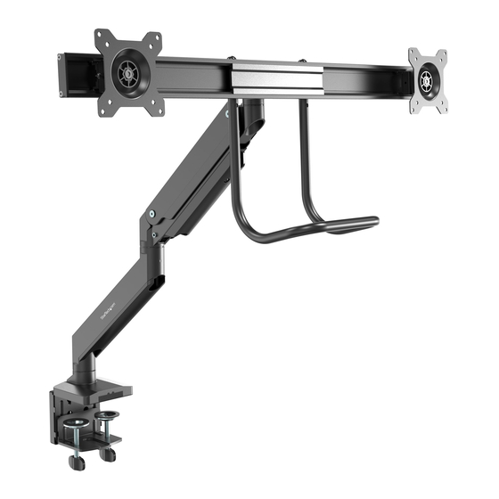
Page 7: Product Diagram
Product Diagram Front View VESA Mount x 2 Grommet Clamp Upper Arm Grab Handle Lower Arm Crossbar C-Clamp To view manuals, videos, drivers, downloads, technical drawings, and more visit www.startech.com/support... -
Page 8: Product Dimensions
Product Dimensions Actual product may vary from image To view manuals, videos, drivers, downloads, technical drawings, and more visit www.startech.com/support... -
Page 9: Product Rotation
Product Rotation To view manuals, videos, drivers, downloads, technical drawings, and more visit www.startech.com/support... -
Page 10: Product Information
Product Information Package Contents Base Lower Arm Qty: 1 Qty: 1 Upper Arm Crossbar Qty: 1 Qty: 1 To view manuals, videos, drivers, downloads, technical drawings, and more visit www.startech.com/support... - Page 11 VESA Mount Grab Handle Qty: 2 Qty: 1 Grommet Plate Base Plate Qty: 1 Qty: 1 Adhesive Foam Pad Base Cable Management Clip Qty: 1 Qty: 1 To view manuals, videos, drivers, downloads, technical drawings, and more visit www.startech.com/support...
- Page 12 Flat Head Hex Screw Qty: 4 Qty: 2 3 mm Hex Key 4 mm Hex Key Qty: 1 Qty: 1 6 mm Hex Key Washer Qty: 1 Qty: 8 To view manuals, videos, drivers, downloads, technical drawings, and more visit www.startech.com/support...
- Page 13 M4 x 12 mm Screws M5 x 12 mm Screws Qty: 8 Qty: 8 Upper C-Clamp Lower C-Clamp Qty: 1 Qty: 1 Button Head Hex Screws Grommet Screw Qty: 4 Qty: 1 To view manuals, videos, drivers, downloads, technical drawings, and more visit www.startech.com/support...
-
Page 14: Technical Specifications
Technical Specifications 75 x 75 100 x 100 VESA 17.6 lb. (2 x 8 kg) Weight Max. 32 “ Screen Size - 180 to + 180 Rotation To view manuals, videos, drivers, downloads, technical drawings, and more visit www.startech.com/support... - Page 15 - 10 to + 10 Tilt - 10 to + 10 Swivel To view manuals, videos, drivers, downloads, technical drawings, and more visit www.startech.com/support...
-
Page 16: Requirements
Requirements Phillips Head Screwdriver x 1 • Displays x 2 • To view manuals, videos, drivers, downloads, technical drawings, and more visit www.startech.com/support... -
Page 17: Assembling The Monitor Mount Using The C-Clamp
Aligning the Upper C-Clamp with the Base Insert the Countersunk Hex Screws through the Screw Holes on the Upper C-Clamp and into the Screw Holes on the bottom of the Base. To view manuals, videos, drivers, downloads, technical drawings, and more visit www.startech.com/support... - Page 18 Screws being careful not to over-tighten. Remove the backing from the Adhesive Foam Pad. Removing the Adhesive Backing Carefully apply the Adhesive Foam Pad to the bottom side To view manuals, videos, drivers, downloads, technical drawings, and more visit www.startech.com/support...
- Page 19 Upper C-Clamp. Applying the Adhesive Foam Pad Using the 4 mm Hex Key, loosen the four Screws on the back of the Lower C-Clamp. To view manuals, videos, drivers, downloads, technical drawings, and more visit www.startech.com/support...
- Page 20 Upper C-Clamp. Slide the Screws down into the small portion of the Screw Holes. Attaching the Lower and Upper C-Clamp Using the 4 mm Hex Key, tighten the four Screws, to create the C-Clamp Assembly. To view manuals, videos, drivers, downloads, technical drawings, and more visit www.startech.com/support...
- Page 21 Screws in either the top four Screw Holes on the C-Clamp Assembly for a thickness range of 10 - 50 mm or the bottom four Screw Holes for a thickness range of 35 - 80 mm. To view manuals, videos, drivers, downloads, technical drawings, and more visit www.startech.com/support...
- Page 22 From underneath the Mounting Surface, tighten the two Thumb Screws at the bottom of the C-Clamp Assembly. Tighten the Thumb Screws until the C-Clamp Plate is pressed tightly against the bottom of the Mounting Surface. To view manuals, videos, drivers, downloads, technical drawings, and more visit www.startech.com/support...
- Page 23 C-Clamp Assembly, securing the Base Cable Management Clip in place. Note: Once you are finished using the Hex Keys they can be stored in the back of the Cable Management Clip. To view manuals, videos, drivers, downloads, technical drawings, and more visit www.startech.com/support...
- Page 24 Installing Base Cable Management Clip Align the bottom of the Lower Arm with the Mounting Peg on the Base. Insert the bottom of the Lower Arm onto the Mounting Peg. To view manuals, videos, drivers, downloads, technical drawings, and more visit www.startech.com/support...
- Page 25 Screws on the Lower Arm. Tighten only the bottom Screw to allow the arm to rotate + or - 180 . Tighten both Screws to allow the arm to rotate + or - 90 To view manuals, videos, drivers, downloads, technical drawings, and more visit www.startech.com/support...
- Page 26 Mounting Peg on the Upper Arm with the Mounting Hole on the Lower Arm. Insert the Mounting Peg on the Upper Arm into the Mounting Hole on the Lower Arm. To view manuals, videos, drivers, downloads, technical drawings, and more visit www.startech.com/support...
- Page 27 Installing the Upper Arm onto the Lower Arm Use the Flat Head Screwdriver End on the 3 mm Hex Key to tighten the Screw on the Lower Arm. To view manuals, videos, drivers, downloads, technical drawings, and more visit www.startech.com/support...
- Page 28 Securing the Upper Arm Align the Screw Holes on the Crossbar (x 4) with the Screw Holes on the Mount on the Upper Arm. To view manuals, videos, drivers, downloads, technical drawings, and more visit www.startech.com/support...
- Page 29 Holes on the Crossbar and into the Screw Holes on the Mount. Using the 4 mm Hex Key, tighten the Button Head Hex Screws, being careful not to over-tighten. To view manuals, videos, drivers, downloads, technical drawings, and more visit www.startech.com/support...
- Page 30 Screw Hole on the Crossbar. The Grab Handle can be mounted at three different heights depending on which Screw Holes you use on the Grab Handle and Crossbar. To view manuals, videos, drivers, downloads, technical drawings, and more visit www.startech.com/support...
- Page 31 Holes on the Crossbar. The Flat Head Hex Screw location will determine the height of the Grab Handle. Repeat steps 25 - 26 to install the second Flat Head Hex Screw. To view manuals, videos, drivers, downloads, technical drawings, and more visit www.startech.com/support...
-
Page 32: Using The Grommet Mount
Installing the Grab Handle Using the Grommet Mount Align the Screw Holes (x 4) on the Base Plate with the Screw Holes on the bottom of the Base. To view manuals, videos, drivers, downloads, technical drawings, and more visit www.startech.com/support... - Page 33 Aligning the Base Plate with the Base Insert the Countersunk Hex Screws through the Screw Holes on the Base Plate and into the Screw Holes on the bottom of the Base. To view manuals, videos, drivers, downloads, technical drawings, and more visit www.startech.com/support...
- Page 34 Using the 4 mm Hex Key tighten the Countersunk Hex Screws being careful not to over-tighten. Remove the backing from the Adhesive Foam Pad. Removing the Adhesive Backing To view manuals, videos, drivers, downloads, technical drawings, and more visit www.startech.com/support...
- Page 35 Align the Grommet Hole on the bottom of the Base with the Grommet Hole on the Mounting Surface. From underneath the Mounting Surface, align the center hole on the Grommet Plate with the Grommet Hole on the Base. To view manuals, videos, drivers, downloads, technical drawings, and more visit www.startech.com/support...
- Page 36 Grommet Hole and into the Grommet Hole on the Base. Use the 6 mm Hex Key to tighten the Grommet Screw until the Grommet Plate is pressed tightly against the bottom of the Mounting Surface. To view manuals, videos, drivers, downloads, technical drawings, and more visit www.startech.com/support...
- Page 37 Tightening the Grommet Screw Align the bottom of the Lower Arm with the Mounting Peg on the Base. Insert the bottom of the Lower Arm onto the Mounting Peg. To view manuals, videos, drivers, downloads, technical drawings, and more visit www.startech.com/support...
- Page 38 Screws on the Lower Arm. Tighten only the bottom Screw to allow the arm to rotate + or - 180 . Tighten both Screws to allow the arm to rotate + or - 90 To view manuals, videos, drivers, downloads, technical drawings, and more visit www.startech.com/support...
- Page 39 Mounting Peg on the Upper Arm with the Mounting Hole on the Lower Arm. Insert the Mounting Peg on the Upper Arm into the Mounting Hole on the Lower Arm. To view manuals, videos, drivers, downloads, technical drawings, and more visit www.startech.com/support...
- Page 40 Installing the Upper Arm onto the Lower Arm Use the Flat Head Screwdriver End on the 3 mm Hex Key to tighten the Screw on the Lower Arm. To view manuals, videos, drivers, downloads, technical drawings, and more visit www.startech.com/support...
- Page 41 Securing the Upper Arm Align the Screw Holes on the Crossbar (x 4) with the Screw Holes on the Mount on the Upper Arm. To view manuals, videos, drivers, downloads, technical drawings, and more visit www.startech.com/support...
- Page 42 Holes on the Crossbar and into the Screw Holes on the Mount. Using the 4 mm Hex Key, tighten the Button Head Hex Screws, being careful not to over-tighten. To view manuals, videos, drivers, downloads, technical drawings, and more visit www.startech.com/support...
- Page 43 Screw Hole on the Crossbar. The Grab Handle can be mounted at three different heights depending on which Screw Holes you use on the Grab Handle and Crossbar. To view manuals, videos, drivers, downloads, technical drawings, and more visit www.startech.com/support...
- Page 44 Holes on the Crossbar. The Flat Head Hex Screw Location will determine the height of the Grab Handle. Repeat steps 19 - 20 to install the second Flat Head Hex Screw. To view manuals, videos, drivers, downloads, technical drawings, and more visit www.startech.com/support...
-
Page 45: Mounting The Monitors
Mount can support 75 x 75 or 100 x 100 mounting pattern. Note When attached, the Notch on the VESA Mount should be along the bottom edge of the Monitors. To view manuals, videos, drivers, downloads, technical drawings, and more visit www.startech.com/support... - Page 46 Note: Do not over-tighten the Screws. If you encounter re- sistance while you’re tightening the Screws, stop tightening. Failure to do so could result in damage to the Monitor. To view manuals, videos, drivers, downloads, technical drawings, and more visit www.startech.com/support...
- Page 47 Crossbar. While supporting the weight of the Monitor, align the VESA Mount on the back of the Monitor with the VESA Holder on the Crossbar. To view manuals, videos, drivers, downloads, technical drawings, and more visit www.startech.com/support...
- Page 48 Slide the VESA Mount down overtop of the VESA Holder. While holding the Monitor in place, use a Phillips Head Screwdriver to tighten the VESA Mount Adjustment Screw on the side of the VESA Mount. To view manuals, videos, drivers, downloads, technical drawings, and more visit www.startech.com/support...
- Page 49 Do not rotate the Monitors over the rear edge of the Mounting Surface as this will create a tipping hazard with potential for equipment or personal damage. Do Not Rotate Monitors Over Rear Edge To view manuals, videos, drivers, downloads, technical drawings, and more visit www.startech.com/support...
-
Page 50: Adjusting The Spring Arm Tension
Upper Arm clockwise (decreasing tension) or counter clockwise (increasing tension). Adjusting the Spring Arm Tension The Upper Arm (spring arm) should only be placed in a horizontal position. To view manuals, videos, drivers, downloads, technical drawings, and more visit www.startech.com/support... -
Page 51: Adjusting The Rotation
Use the 4 mm Hex Key to loosen the four Screws on the back of the VESA Mount. Adjust the rotation of the Crossbar +4 or -4 Use the 4 mm Hex Key to retighten the four Screws. To view manuals, videos, drivers, downloads, technical drawings, and more visit www.startech.com/support... -
Page 52: Making Micro-Adjustments
Screwdriver to loosen the VESA Mount Adjustment Screw on the side of the VESA Mount. Using a Phillips Head Screwdriver adjust the Micro- Adjustment Screw on the bottom of the VESA Mount. To view manuals, videos, drivers, downloads, technical drawings, and more visit www.startech.com/support... -
Page 53: Routing The Cables
Cable Cover, located underneath the Upper Arm and unhook the Retention Hook to remove the Cable Cover. Slide the Cable Cover on the Lower Arm up in order to remove the Cable Cover. To view manuals, videos, drivers, downloads, technical drawings, and more visit www.startech.com/support... - Page 54 Replace the Screw removed in step 1 and hook the Retention Hook, securing the Cable Cover to the Upper Arm. Route the Monitor Cables down the inside of the Lower Arm. To view manuals, videos, drivers, downloads, technical drawings, and more visit www.startech.com/support...
- Page 55 Replacing the Cable Covers Slide the Cable Cover down the inside of the Lower Arm to secure it. To view manuals, videos, drivers, downloads, technical drawings, and more visit www.startech.com/support...
- Page 56 Limitation of Liability In no event shall the liability of StarTech.com Ltd. and StarTech.com USA LLP (or their officers, directors, employees or agents) for any damages (whether direct or indirect, special, punitive, incidental, consequential, or otherwise), loss of profits, loss of business, or any pecuniary loss, arising out of or related to the use of the product exceed the actual price paid for the product.
- Page 57 StarTech.com is an ISO 9001 Registered manufacturer of connectivity and technology parts. StarTech.com was founded in 1985 and has operations in the United States, Canada, the United Kingdom and Taiwan servicing a worldwide market.
Need help?
Do you have a question about the ARMSLMBARDUO and is the answer not in the manual?
Questions and answers