Table of Contents
Advertisement
Quick Links
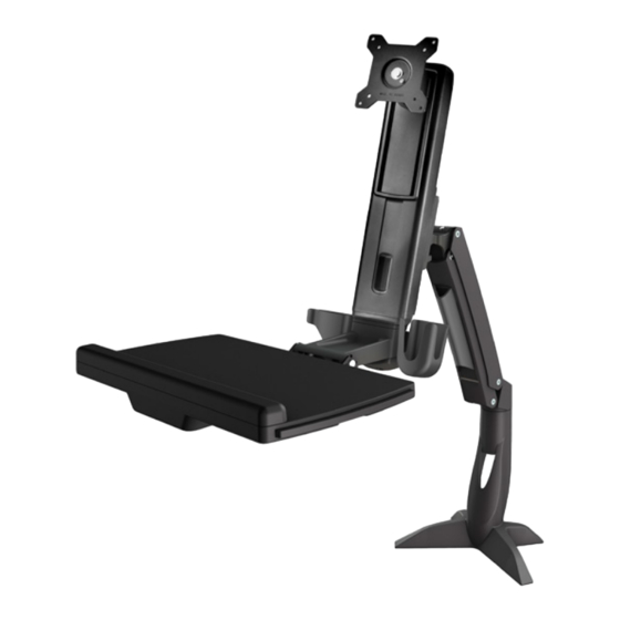
Sit-Stand Arm - Single Monitor
ARMSTSCP1
*actual product may vary from photos
FR: Guide de l'utilisateur - fr.startech.com
DE: Bedienungsanleitung - de.startech.com
ES: Guía del usuario - es.startech.com
NL: Gebruiksaanwijzing - nl.startech.com
PT: Guia do usuário - pt.startech.com
IT: Guida per l'uso - it.startech.com
JP: 取扱説明書 - jp.startech.com
For the most up-to-date information, please visit: www.startech.com
Manual Revision: 05/14/2021
Advertisement
Table of Contents

Related Manuals for StarTech.com ARMSTSCP1


Summary of Contents for StarTech.com ARMSTSCP1
- Page 1 DE: Bedienungsanleitung - de.startech.com ES: Guía del usuario - es.startech.com NL: Gebruiksaanwijzing - nl.startech.com PT: Guia do usuário - pt.startech.com IT: Guida per l’uso - it.startech.com JP: 取扱説明書 - jp.startech.com For the most up-to-date information, please visit: www.startech.com Manual Revision: 05/14/2021...
- Page 2 StarTech.com. Where they occur these references are for illustrative purposes only and do not represent an endorsement of a product or service by StarTech.com, or an endorsement of the product(s) to which this manual applies by the third-party company in question. Regardless of any direct acknowledgement elsewhere in the body of this document, StarTech.com hereby...
- Page 3 Warning statements Dichiarazioni di avvertenza Make sure that you assemble this product according to the instructions. Assicurarsi di Assemblare il prodotto secondo le istruzioni. Read the entire manual and make sure that you understand the instructions before you start to Leggere l’intero manuale e assicurarsi di aver compreso tutte le istruzioni prima di iniziare ad assemblare assemble and use this product.
- Page 4 注意 必ず取扱説明書に従って本製品の組み立てを行って下さい。 最初に取扱説明書を最後まで読み、 本製品の組み立て方をすべて理解してから組み立て作業を 始めて下さい。 本製品は、 室内での使用を想定しています。 戸外では使用しないで下さい。 本製品は、 二人がかりでの組み立てを想定しています。 手助けなしに単独で組み立てと設置を行 わないで下さい。 モニタの重量が本製品の最大積載重量を超えないようにして下さい。 最大積載重量をオーバーした場 合、 怪我をする恐れや器物破損の恐れがあります。 グロメッ ト固定方式を使用した場合のモニタアームの耐荷重 : 2-8 kg. グロメッ ト固定方式を使用した場合のキーボードトレイの耐荷重 : 2.5 kg. クランプ固定方式を使用した場合のモニタアームの耐荷重 : 2-8 kg. クランプ固定方式を使用した場合のキーボードトレイの耐荷重 : 1.5 kg. 反動注意 ! 本製品には、 リフト機構が組み込まれており、 積載した装置を取り外すと反動で急激に上昇 する可能性があります。 装置を取り外す前に、 本製品を最も高い位置に移動させて下さい。 この操作を 怠ると怪我をする恐れや器物破損の恐れがあります。...
-
Page 5: Table Of Contents
Attach the adhesive strip ........................38 Route cables ..............................39 Remove the monitor ................40 Adjusting the ARMSTSCP1..............41 Adjust the tilt angle of the monitor ....................41 Adjust the tilt angle of the keyboard tray ..................42 Counterbalance the weight of the monitor ..................43 Counterbalance the weight of the workstation ................ - Page 6 Clean the keyboard tray ................47 Technical support ...................48 Warranty information ................48 Instruction manual...
-
Page 7: Product Dimensions
Product dimensions Max 940 mm (37 in.) 351 mm to 530 mm 408.7 mm (16.1 in.) (13.8 in. to 20.9 in.) 166 mm (6.5 in.) 32.5 mm (1.3 in.) 8 mm to 65 mm (0.3 in. to 2.6 in.) 124 mm (4.9 in.) 88 mm (3.5 in.) - Page 8 773.2 mm (30.4 in.) 285 mm (11.2 in.) 100 mm (3.9 in.) 75 mm (2.9 in.) 4.5 mm (0.2 in.) Instruction manual...
- Page 9 8 to 217 mm 8 to 217 mm 449 mm (17.7 in.) (0.3 in. to 8.5 in.) (0.3 in. to 8.5 in.) 668 mm (26.3 in.) 530 mm (20.9 in.) 351 mm (13.8 in.) 489 mm (19.2 in.) Instruction manual...
-
Page 10: Product Diagram
Product diagram Grommet feature pictured VESA monitor mount Column Monitor arm Keyboard tray Base Instruction manual... -
Page 11: Technical Specifications
Technical specifications Type of measurement Measurement 75 x 75 mm 100 x 100 mm VESA -5° to +35° Tilt (monitor) 0° to +90° Tilt (keyboard) 360° Pivot (monitor) +/-90° Swivel (monitor arm) Instruction manual... - Page 12 Type of measurement Measurement 24 in. or less Supported monitor size 4.4 to 17.6 lb. (2 to 8 kg) Supported weight of the monitor arm when you use the desk clamp 3.3 lb. (1.5 kg) Supported weight of the keyboard tray when you use the desk clamp 4.4 to 17.6 lb.
-
Page 13: Package Contents
Package contents Monitor arm Keyboard tray Qty: One Qty: One Column VESA monitor mount Qty: One Qty: One Base Adhesive strip Qty: One Qty: Two Instruction manual... - Page 14 Socket driver 6 mm hex key Qty: One Qty: One M6x10 mm screw M8x20 mm screws Qty: Three Qty: One Metal washer Plastic washer Qty: One Qty: One Instruction manual...
- Page 15 Basic screw M6x25 mm screws Qty: Two Qty: Four 5 mm hex key M6x12 mm screw Qty: One Qty: Four M4x10 mm hex key 2.5 mm hex key Qty: Four Qty: One Instruction manual...
- Page 16 M6x8 mm screw Base Pad Qty: One Qty: One Clamp screws Base plate Qty: Four Qty: One Grommet plate M8x65 screw Qty: One Qty: One Instruction manual...
-
Page 17: Requirements
Qty: One Qty: One Requirements • Monitor that is compatible with one of the VESA mounting hole patterns that ARMSTSCP1 supports • Phillips type screwdriver • ¹/₄ inch drive ratchet Requirements are subject to change. For the latest requirements, please visit www.StarTech.com/ARMSTSCP1. -
Page 18: Assembly
• At least 0.3 inches (8 mm) of clearance between the table or desk and the wall • Monitor that weighs between 4.4 and 17.6 lb. (2 to 8 kg) Note: When you use the desk clamp to attach the ARMSTSCP1, the keyboard tray supports up to 3.3 lb. (1.5 kg) of weight. -
Page 19: Assemble The Base Attachment
Assemble the base attachment Based on your setup, follow the steps to attach the grommet assembly or the desk clamp. Attach the grommet assembly 1. Line up the base plate with the assembly holes on the underside of the base. 2. - Page 20 4. Remove the adhesive backing from the base pad and affix the base pad to the underside of the base. (figure 2) figure 2 Base Base pad Instruction manual...
- Page 21 5. Position the base over the grommet hole in your desk or table. 6. Thread the M8x65 screw up through the underside of the grommet plate. 7. Place the grommet plate and screw assembly against the grommet hole on the underside of your desk or table.
- Page 22 Attach the desk clamp to a desk or table against a wall To attach the desk clamp to a desk or table that is against a wall, you need at least 8 mm of space between the edge of the surface that you’re attaching the ARMSTSCP1 to and the wall.
- Page 23 4. Remove the adhesive backing from the base pad and affix the base pad to the underside of the clamp L bracket. (figure 5) figure 5 Base Base pad Clamp L bracket Instruction manual...
- Page 24 5. Slide the base between the desk or table and the wall. (figure 6) figure 6 Base Min 8 mm Instruction manual...
- Page 25 6. Align the four holes in the clamp screw assembly with the four lower holes in the clamp L bracket. (figure 7) figure 7 Clamp screw assembly Clamp L bracket Instruction manual...
- Page 26 7. Insert four clamp screws through the clamp screw assembly and into the four lower screw holes, located in the clamp L bracket. Note: The four lower screw holes must be used to achieve the full 8 mm - 65 mm clamp mounting range.
- Page 27 9. Use the 6 mm hex key to tighten the screws in the clamp screw assembly until the plates are tight against your desk or table. (figure 9) figure 9 Plate Screw 6 mm hex key Instruction manual...
- Page 28 Attach the desk clamp to a desk or table 1. Line up the clamp L bracket with the assembly holes on the underside of the base. 2. Insert the four base screws through the base plate and into the base. (figure 10) 3.
- Page 29 4. Remove the adhesive backing from the base pad and affix the base pad to the underside of the base. (figure 11) figure 11 Base Base pad Clamp L bracket Instruction manual...
- Page 30 5. Align the four holes in the clamp screw assembly with the four lower holes in the clamp L bracket. 6. Insert four clamp screws through the clamp screw assembly and into the four lower screw holes, located in the clamp L bracket. Note: The four lower screw holes must be used to achieve the full 8 mm - 65 mm clamp mounting range.
- Page 31 8. Slide the assembly over the edge of your desk or table. (figure 13) figure 13 Base 8 and 65 mm Instruction manual...
- Page 32 9. Use the 6 mm hex key to tighten the screws in the clamp screw assembly until the plates are tight against your desk or table. (figure 14) figure 14 Plate Screw 6 mm hex key Instruction manual...
-
Page 33: Attach The Monitor Arm To The Base
Attach the monitor arm to the base 1. Place the monitor arm onto the projection on the base. 2. Place the plastic washer into the joint in the monitor arm. 3. Place the metal washer onto the plastic washer. 4. Insert the M8x20 mm screw through the washers and into the joint in the monitor arm. -
Page 34: Attach The Column To The Keyboard Tray
Attach the column to the keyboard tray 1. Position the column with the cutout at the bottom half of the column. 2. Line up the assembly holes on the bottom of the column with the assembly holes between the holders on the keyboard tray. (figure 16) figure 16 Column Holder... - Page 35 3. On the underside of the keyboard tray, insert the four M6x12 mm screws through the keyboard tray and into the column. (figure 17) 4. Use the 5 mm hex key to tighten the screws in place. figure 17 5 mm hex key M6x12 mm screw Keyboard tray Instruction manual...
- Page 36 5. On the underside of the keyboard tray, place the keyboard tray cap over the assembly holes. 6. Insert the two M6x25 mm screws into the keyboard tray cap and keyboard tray. (figure 18) 7. Use the 5 mm hex key to tighten the screws in place. figure 18 5 mm hex key M6x25 mm screw...
-
Page 37: Attach The Column To The Monitor Arm
Attach the column to the monitor arm 1. Insert one of the M6x10 mm screws into the top hole in the plate on the back of the column. (figure 19) Note: Do not tighten the M6x10 mm screw and make sure that you leave between 4 and 5 mm of space between the plate and the screw. - Page 38 2. Hook the M6x10 mm screw attached to the column into the key-shaped hole at the top of the plate on the monitor arm. (figure 20) figure 20 M6x10 mm screw Key-shaped hole Monitor arm Instruction manual...
- Page 39 3. Insert the M6x10 mm screws into the lower two holes on the plate on the monitor arm. (figure 21) 4. Use the 5 mm hex key to tighten all three of the screws. figure 21 Monitor arm M6x10 mm screw 5 mm hex key Instruction manual...
-
Page 40: Attach The Vesa Monitor Mount To A Monitor
Attach the VESA monitor mount to a monitor 1. If you want to be able to rotate your monitor 360°, use a Phillips type screwdriver to remove the screw from the VESA monitor mount. (figure 22) figure 22 VESA monitor mount Screw Screwdriver Instruction manual... - Page 41 2. Position the VESA monitor mount so that the projection on the back of the VESA monitor mount is pointing towards the bottom of the monitor. 3. Line up the VESA monitor mount with the mounting holes on the back of the monitor.
-
Page 42: Attach The Monitor To The Column
Attach the monitor to the column 1. Carefully hook the back of the VESA monitor mount onto the plate on the column. (figure 24) figure 24 VESA monitor mount Column Instruction manual... - Page 43 2. Insert the M6x8 mm screw through the bottom of the VESA monitor mount and into the plate on the column. (figure 25) 3. Use the 5 mm hex key to tighten the screw. figure 25 VESA monitor mount M6x8 mm screw 5 mm hex key Instruction manual...
-
Page 44: Attach The Adhesive Strip
Attach the adhesive strip 1. If necessary, cut the adhesive strip to fit the length of your keyboard. 2. Separate the two sides of the adhesive strip. 3. Remove the backing from one half of the adhesive strip and stick it to the back of your keyboard. -
Page 45: Route Cables
Route cables 1. Run your cable along the column and through the slot at the bottom of the column. 2. At the top of the cable cover, squeeze the tabs and gently pull the cable cover from the monitor arm. 3. -
Page 46: Remove The Monitor
2. Use the M5 hex key to remove the M6x8 mm screw from the bottom of the VESA monitor mount. 3. Carefully lift the monitor off of the monitor mount. figure 28 Monitor ARMSTSCP1 in upright position 5 mm hex key Instruction manual... -
Page 47: Adjusting The Armstscp1
Adjusting the ARMSTSCP1 Adjust the tilt angle of the monitor • To increase or decrease the tilt, use the 2.5 mm hex key and adjust the screw in the top of the VESA monitor mount. (figure 29) figure 29 VESA monitor mount Adjustment screw 2.5 mm hex key... -
Page 48: Adjust The Tilt Angle Of The Keyboard Tray
Adjust the tilt angle of the keyboard tray • Pull up or push down on the keyboard tray to adjust it from 0 to 90°. (figure 30) figure 30 Keyboard tray Instruction manual... -
Page 49: Counterbalance The Weight Of The Monitor
Counterbalance the weight of the monitor The ARMSTSCP1 features a one-touch height adjustment design that enables you to easily raise or lower your monitor. To use the one-touch height adjustment feature, you need to counterbalance the weight of your monitor. -
Page 50: Counterbalance The Weight Of The Workstation
Counterbalance the weight of the workstation The ARMSTSCP1 features a one-touch height adjustment design that enables you to easily raise or lower the entire workstation, including the keyboard tray. To use the one-touch height adjustment feature, you need to counterbalance the weight of the workstation. -
Page 51: Adjust The Swivel Effort Of The Monitor Arm
Adjust the swivel effort of the monitor arm • To increase or decrease the swivel effort of the monitor arm, use the 6 mm hex key to turn the screw in the plate on the back of the column to the right or left. (figure 33) Caution! When you loosen the screw, make sure that you don’t remove the screw from the joint. -
Page 52: Extend The Keyboard Tray
Extend the keyboard tray You can adjust the keyboard tray so that it extends to the left or right. • Pull the extension to the left or right. (figure 34) figure 34 Keyboard tray Extension Extension Instruction manual... - Page 53 Clean the keyboard tray You can remove the extension and the plastic cover from the wrist rest to clean them. 1. To remove the plastic cover from the wrist rest, carefully peel it off of the keyboard tray. (figure 35) 2.
- Page 54 Limitation of liability In no event shall the liability of StarTech.com Ltd. and StarTech.com USA LLP (or their officers, directors, employees or agents) for any damages (whether direct or indirect, special, punitive, incidental, consequential, or otherwise), loss of profits, loss of business, or any pecuniary loss, arising out of or related to the use of the product exceed the actual price paid for the product.
- Page 55 Hard-to-find made easy. At StarTech.com, that isn’t a slogan. It’s a promise. StarTech.com is your one-stop source for every connectivity part you need. From the latest technology to legacy products — and all the parts that bridge the old and new — we can help you find the parts that connect your solutions.
Need help?
Do you have a question about the ARMSTSCP1 and is the answer not in the manual?
Questions and answers