Advertisement
Quick Links
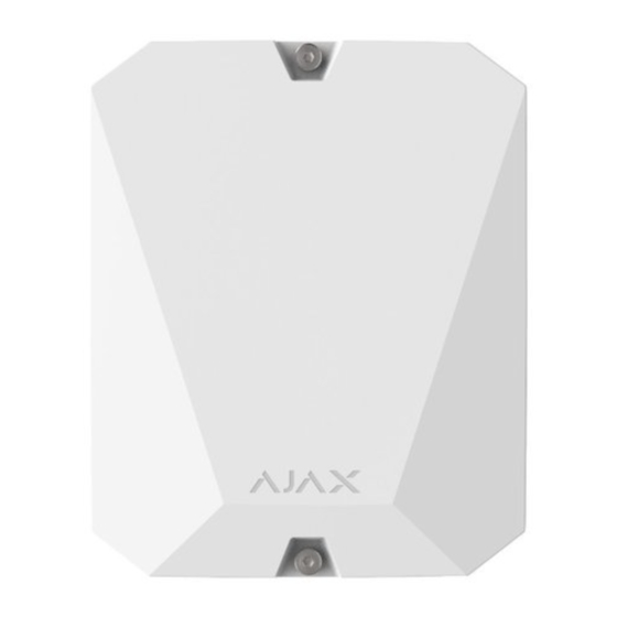
vhfBridge User Manual
Updated December 10, 2021
vhfBridge is a module for connecting Ajax security systems to third-party VHF
transmitters. It provides 8 transistor outputs for connection to third-party VHF
transmitters.
The device is powered from 100–240V ~ mains and can be operated from a
12V⎓ backup battery.
The vhfBridge operates as part of the Ajax security system by connecting via
the
Jeweller
secure radio communication protocol to the hub. The hub
communication range is up to 1800 meters without obstacles. Comes in two
con gurations: with and without a casing.
Buy vhfBridge
Functional elements
Body elements
Advertisement

Subscribe to Our Youtube Channel
Related Manuals for AJAX vhfBridge


Summary of Contents for AJAX vhfBridge
- Page 1 The device is powered from 100–240V ~ mains and can be operated from a 12V⎓ backup battery. The vhfBridge operates as part of the Ajax security system by connecting via Jeweller secure radio communication protocol to the hub. The hub communication range is up to 1800 meters without obstacles.
- Page 2 5. Perforated part of the body for the output of wires of connected detectors and devices. The presence of the casing depends on the vhfBridge package. Devices come in two con gurations: with and without a casing. vhfBridge board elements...
- Page 3 1. Terminals for connecting a 12 V⎓ backup battery. 2. Power supply input 100–240 V~. 3. Tamper button. Signals if vhfBridge body lid is removed. 4. Power button. 5. LED indicator. 6. QR code and ID (serial number) of the device.
-
Page 4: Led Indication
Please note that the LED indicator is not visible when the body lid is closed. The LED indicator is used at the stage of connecting and con guring the vhfBridge. In the future, the state of the device can be monitored in the Ajax app. -
Page 5: Operating Principle
VHF transmitters to create an additional channel for transmitting events to the CMS. The communication channel with the CMS created using vhfBridge can be used as the only or as a backup channel for communicating with the CMS (more reliable option). - Page 6 The VHF transmitter, in turn, transmits all events and alarms to the CMS via a radio channel. Events can be transmitted to the CMS via the internet and vhfBridge in parallel. Transmission via the internet works as the main channel because of greater reliability and informativity.
- Page 7 (low-potential output) works the other way around. In the normal state, the voltage is maintained at 12–14 V⎓, and when an alarm or event occurs, the voltage drops to 0 V. The vhfBridge output type and alarm pulse duration are con gurable in Ajax apps. VHF transmitter power supply vhfBridge can supply a third-party VHF transmitter with 12 V⎓...
-
Page 8: Adding To The System
Ajax app 2. Go to the Devices menu. 3. Select vhfBridge. The loop (zone) number is displayed at the very bottom of the page. The vhfBridge loop (zone) number is also available in the Groups menu (Ajax app → Devices →... - Page 9 4. Click Add; the countdown will begin. 5. Switch on vhfBridge by holding the power button for 3 seconds. Keep in mind that the hub connection request is only transmitted when the integration module is switching on.
- Page 10 Faults counter When a vhfBridge malfunction is detected (e.g., no external power), the Ajax app will display a red icon with a number in the upper left corner of the device icon. The number indicates the number of faults. All faults can be seen in the transponder states. Fields with faults will be highlighted in red.
- Page 11 Icons display some vhfBridge states. You can view them in the Ajax app, in the Devices tab. Icon Meaning Jeweller Signal Strength. Displays the signal strength between the hub and vhfBridge. The recommended value is 2-3 bars. The charge level of the battery connected to vhfBridge.
- Page 12 O ine — no connection to the device ReX “range extender name” Please note that the eld is displayed if radio signal vhfBridge is operated via a range extender Temporary Deactivation Shows the status of the device temporary deactivation function:...
- Page 13 The device does not follow system commands and does not report alarms or other events Firmware vhfBridge rmware version. vhfBridge ID (serial number). Also located on the device box, its board, and the body. Device № Number of the device loop (zone). vhfBridge settings...
- Page 14 Note that after editing the settings, you should click the Back button to save them. Setting Meaning vhfBridge name. It is displayed in the text of SMS and noti cations in the event feed. To change the device name, click on the pencil...
- Page 15 5th output — loss of vhfBridge power supply 6th output — power loss of the hub 7th output — hub battery discharged 8th output — loss of communication between the hub and vhfBridge The settings of outputs can be changed in the Ajax app...
- Page 16 1. Go to the Devices tab. 2. Find vhfBridge in the list of devices. 3. Go to the Outputs menu. 4. Find the output in the list and go to its Settings by clicking on the gear icon 5. Set the required parameters.
- Page 17 Fire Fire alarm Medical alarm Medical alarm Button Panic button clicking in Ajax apps Clicking DoubleButton Clicking Button in panic Panic button button mode Clicking a panic button connected to Transmitter or MultiTransmitter Alarm of any connected Any alarm detector...
- Page 18 Transponder battery vhfBridge battery discharged discharged Power loss of the hub Loss of hub main power Hub battery discharged The hub battery is discharged Tamper triggering of any device Changing the security mode of Change of security modes an object or a group (bistable...
- Page 19 Learn more Loss of vhfBridge connection Lost connection with vhfBridge with the hub via Jeweller channel The following vhfBridge outputs work in the bistable mode: Arming status Hub power vhfBridge power Hub battery status vhfBridge battery status All other outputs work in the pulse mode.
- Page 20 How to connect a VHF transmitter to vhfBridge When connecting the VHF transmitter, do not twist the wires together, but solder them. The ends of the VHF transmitter wires, which will be inserted into the vhfBridge terminals should be tinned or crimped with a special sleeve.
- Page 21 8. Connect power to vhfBridge. 9. Turn on vhfBridge. vhfBridge functionality testing Integration module functionality tests do not begin immediately, but not later than over a single ping period of the hub — detector (36 seconds with the standard settings of the hub). You can change the ping period of devices in the Jeweller menu of the hub settings.
- Page 22 When choosing the installation location, consider the distance between vhfBridge and the VHF transmitter — the cable length should be su cient for connection. The minimum distance between vhfBridge and the radio transmitter is 2 meters and the maximum distance is 7 meters.
- Page 23 2. Install the vhfBridge card into the body on the racks. If available, connect a backup battery. Note that a power supply should not be connected to the terminals.
-
Page 24: Maintenance
Maintenance Check the functionality of vhfBridge regularly. The optimal frequency of checks is once every three months. Clean the body from dust, cobwebs, and other contaminants as they emerge. Use a soft, dry cloth that is suitable for equipment care. - Page 25 Compatible with central units Hub 2 Hub Plus Hub 2 Operates with Plus Compatible with range extenders Connections Jeweller: two-sided encrypted radio protocol Communication protocol that transmits events and alarms Up to 1,800 meters in a line of sight Radio signal range Learn more 868,0−868,6 МГц...
-
Page 26: Complete Set
5. Body (depends on the con guration). 6. Quick Start Guide. Warranty Warranty for the AJAX SYSTEMS MANUFACTURING Limited Liability Company products is valid for 2 years after the purchase. If the device does not work correctly, you should rst contact the support service. - Page 27 User Agreement Contact Technical Support: e-mail Telegram...
Need help?
Do you have a question about the vhfBridge and is the answer not in the manual?
Questions and answers