Table of Contents
Advertisement
Quick Links
Advertisement
Table of Contents

Related Manuals for Sune Technology QVI-Juke 2013


Summary of Contents for Sune Technology QVI-Juke 2013
- Page 1 Your best partner for better driving SUNE TECHNOLOGY CO.,LTD No.9,Lane 606,Anping Rd,Tainan City 70849,TAIWAN TEL:+88662292246 FAX:+88662288104 Http://www.sune-tech.com Shop http://www.carnavi-tech.com SKYPE:sune_tech or hsin_han99 Update Date 2014.02.04 Model QVI-JK13-V1.1 Firmware Date...
- Page 2 Warning / Caution When installing the main unit, do not remove or alter existing vehicle fasteners, including nuts, bolts, screw, clips, and fittings. Never detach, move or alter existing vehicle wiring, including electrical grounds and straps. Alteration of existing vehicle Warning components may make vehicle unsafe to operate.
-
Page 3: Table Of Contents
Table of Contents 1. Specifications 1.1 Main Specifications 1.2 Features 1.3 System Diagram 1.4 Components 1.5 Exterior 2. Installation 2.1 Installation Diagram 2.2 Installation 3. Settings 3.1 Remote Control 3.2 Factory mode 3.2.1 Image, Park 3.2.2 UTIL 3.3 OSD(On Screen Display) 3.3.1 Analog RGB mode 3.3.2 Video mode 4. -
Page 4: Specifications
1. Specifications 1.1 Main Specifications 1. Car Compatibility NISSAN JUKE 2013 Model 2. Components Video Interface* 1EA Touch Sub board* 1EA 3. MULTIMEDIA INTERFACE input specification 2 * A/V input (video external input) 1 * CVBS(Rear Camera) input 1 * Analog RGB input (Navigation system output) 1 * LCD input (Car system input) 4. -
Page 5: Features
1. Specifications 1.2 Features Improved Screen Display (user-oriented interface) Provide power cable to connect with rear camera Possible to select type for Parking assistant line... -
Page 6: System Diagram
1. Specification 1.3 System Diagram Switch for source toggle Remote control NAVIGATION Input (Analog RGB) DISPLAY A/V 1 Car Installation OEM LCD A/V 2 VIDEO MUX VIDEO A/V 3 CIRCUIT CVBS (Rear camera) Car Screen Input (CAR MAIN BOARD) POWER A/V OUT HEADREST CIRCUIT... -
Page 7: Components
1. Specification 1.4 Components REAR CAMERA TOUCH OUT cable * 1ea POWER cable * 1ea RGB cable * 1ea IR cable * 1ea (HTOUCH0004) (HARETC0002) (HNAVIC0004) (HIRCAB0002) MODE cable * 1ea A/V cable * 1ea (HARETC0001) (HAVCAB0017) POWER cable (24P) * 1ea (HPOWER0051) Sub-board * 1ea (QCPASS0477) -
Page 8: Exterior
1. Specifications 1.5 Exterior Dimension Width 134mm Length 84mm ⑦ ⑥ ⑤ Height 9mm ① TOUCH_OUT(OEM) ② COMMAND IN ③ TOUCH_IN(OEM) ④ LCD OUT ⑤ POWER/NAVI/CAN ① ② ⑥ A/V IN ⑦ BUTTON ③ ④... -
Page 9: Installation Diagram
2. Installation 2.1 Installation Diagram <POWER CABLE> CAN-H CAN-L IR-GND TPGGLE SAFE REAR RCAM-PWR REAR-C GND REAR-C GREEN BLUE SYNC ※ Please make sure that the installation should be carefully conducted to avoid from the damage of a monitor by ESD(Electrostatic discharge) and misalignment while connecting the... -
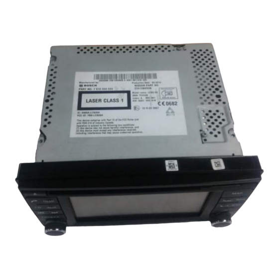
Page 10: Installation
2. Installation 2.2 Installation ① Remove the monitor from the car (see picture above), Separate the LCD and the body part. ※ Please make sure that the installation should be carefully conducted to avoid from the damage of a monitor by ESD(Electrostatic discharge) and misalignment while connecting the module of a monitor with cables. - Page 11 2. Installation 2.2 Installation ① After dismantle the body, assemble provided bracket with bolt on indicated places. ② After assembling the bracket, put provided SUB-BOARD with bolt on indicated places. ※ Please make sure that the installation should be carefully conducted to avoid from the damage of a monitor by ESD(Electrostatic discharge) and misalignment while connecting the module of a monitor with cables.
- Page 12 2. Installation 2.2 Installation ① Separate steel plate on the back of LCD. See picture above. ※ Please make sure that the installation should be carefully conducted to avoid from the damage of a monitor by ESD(Electrostatic discharge) and misalignment while connecting the module of a monitor with cables.
- Page 13 2. Installation 2.2 Installation ① After removing LCD board, separate the original cable on indicated places and connect with provided FFC cable on the other side. ※ Please make sure that the installation should be carefully conducted to avoid from the damage of a monitor by ESD(Electrostatic discharge) and misalignment while connecting the module of a monitor with cables.
- Page 14 2. Installation 2.2 Installation ① After connecting original gold cable with provided touch board, connect with the other side of provided FFC cable (see picture above). ※ Please make sure that the installation should be carefully conducted to avoid from the damage of a monitor by ESD(Electrostatic discharge) and misalignment while connecting the module of a monitor with cables.
- Page 15 2. Installation 2.2 Installation ① Put together the LCD, take out the cable from indicated spot (see picture above). ② Connect the FFC cable (same side) with indicated place (see picture above). ※ Please make sure that the installation should be carefully conducted to avoid from the damage of a monitor by ESD(Electrostatic discharge) and misalignment while connecting the module of a monitor with cables.
- Page 16 2. Installation 2.2 Installation ① Put together the still plate and take out the cable as shown above. And assemble again with the main board. ※ Please make sure that the installation should be carefully conducted to avoid from the damage of a monitor by ESD(Electrostatic discharge) and misalignment while connecting the module of a monitor with cables.
- Page 17 2. Installation 2.2 Installation ① Connect the cables as shown above. ② After connecting cables, assemble the board in order as doing dismantling. ※ Please make sure that the installation should be carefully conducted to avoid from the damage of a monitor by ESD(Electrostatic discharge) and misalignment while connecting the module of a monitor with cables.
-
Page 18: Settings
3. Settings 3.1 Remote Control Function Unavailable POWER & PIP Activating OSD menu MENU Making a selection, changing image display Moving upward ▲ Moving downward ▼ Moving leftward (If you press this button 2 seconds long, you can access the factory ◀... -
Page 19: Factory Mode 3.2.1 Image, Park
3. Settings 3.2.1 Factory mode-Image, Park FACTORY mode – Press ◀ button 2 seconds long on the remote control. IMAGE Adjust navigation position and size H-POSITION : Move display horizontally V-POSITION : Move display vertically PARK PARK ENABLE : Selecting whether to display the parking guide line or not on rear gear (default : OFF) PAS SETUP : Adjusting the position of... - Page 20 3. Settings 3.2.1 Factory mode-Image, Park FACTORY mode – Press ◀ button 2 seconds long on the remote control. Go to Factory Menu, choose PAS SETUP, by using OK button change H-POS → V-POS H-POS In H-POSITION, use ◁, ▷ on remote control, to adjust parking guideline left and right.
-
Page 21: Util
3. Settings 3.2.2 Factory mode-Util FACTORY mode – Press ◀ button 2 seconds long on the remote control. UTIL – NAVI SKIP UTIL – A/V1 SKIP Selecting whether to display RGB Selecting whether to display A/V1 Mode or not Mode or not YES(Not use) / NO(use-Default) YES(Not use) / NO(use-Default) -
Page 22: Osd(On Screen Display)
3. Settings 3.3.1 OSD (On Screen Display) / Analog RGB Mode IMAGE COLOR * BRIGHTNESS * RED * CONTRAST * GREEN * SHARPNESS * BLUE * USER IMAGE : able to make a * USER COLOR : able to make a choice among 4 set-colors of the choice among 4 set-colors of the screen... -
Page 23: Video Mode
3. Settings 3.3.2 OSD (On Screen Display) / Analog RGB Mode OSD IMAGE * TRANSPARENT : Adjust OSD * BRIGHTNESS transparency * CONTRAST * H_POSITION : Move OSD * SATURATION horizontally * HUE * V_POSITION : Move OSD * SHARPNESS vertically * USER IMAGE : able to make a choice... -
Page 24: Trouble Shooting
4. Trouble Shooting Q. I cannot change mode A. Check connection of Ground cable and IR Cable. Check LED lamp is on, if not check connection of POWER cable. Q. All I got on the screen is black. A. .Check second LED lamp of the interface is on, if not, check A/V sources connected are working well.
Need help?
Do you have a question about the QVI-Juke 2013 and is the answer not in the manual?
Questions and answers