Advertisement
Quick Links
Advertisement

Subscribe to Our Youtube Channel
Related Manuals for H-KING Wargo Signature Edge 540T 3D


Summary of Contents for H-KING Wargo Signature Edge 540T 3D
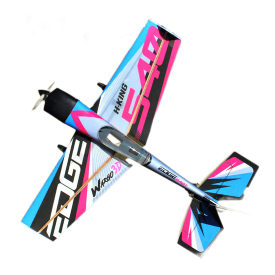
- Page 1 INSTRUCTION MANUAL H-KING WARGO EDGE ” D AEROBATIC PLANE (ARF VERSION)
- Page 2 WARNING Please read this instruction manual fully and become completely familiar with the features of this product before operating. Failure to operate this product correctly could result in damage to the product, personal property and cause serious injury. This is a sophisticated hobby product and is NOT a toy. It must always be operated with caution, common sense and some basic mechanical ability.
- Page 3 My Opinions on this airframe The plane itself is a fantastic overall performer. On 4s it is very agile and athletic. If you like high energy and tumbling, it is the best setup. I fly it mostly on 3S, the lighter setup is a bit better suited for low and slow 3D.
-
Page 4: Specifications
INTRODUCTION The Wargo Signature Edge 540T is the next step of my goal to provide a line of perfect 3D and aerobatic training aircraft. I have dedicated a lot of my flying career to teaching 3D aerobatics and helping pilots learn how to become better pilots. I have also dedicated myself to trying to develop the ideal transition and training 3D plane. - Page 5 CONTENTS 1: Fuselage 9: Landing gear and wheel set assembly 2: Wing set 10: Hardware accessories 3: Elevator 11: Aileron extension cord 4: Rudder 12: Pushrod 5: Landing gear fairings 13: Hook and Loop tape 6: Wheel spats 14: Spinner 7: Side force generator(L+R) 15: Zip ties...
- Page 6 ASSEMBLY Install the rudder servo as shown. Insert the landing gear and landing gear plate into the slot as shown. Use slow curing CA glue for the strongest bond. Dry fit the main wing set and stabilizer onto the fuselage. Use a straight edge to ensure the measurement for both left and right side of the wing tip to the stabilizer...
- Page 7 Once you are satisfied with the fit and the measurements, apply a few drops of foam safe CA glue to the joints between the fuselage and the wing just to hold them in position. Repeat this process for the horizontal stabilizer. Check the measurements once again to ensure they are correct.
- Page 8 Use thin foam CA glue to attach the elevator control horn. Install the control horn plate on the other side of the elevator. Install the tailwheel bracket and glue to the rudder as shown. Adjust the rudder so there is a hinge gap of about 1mm space in between.
- Page 9 Apply foam safe glue to the tailwheel bracket holding plate and glue it to the tail as shown. Connect one of the supplied extension servo leads to an aileron servo and install it into one of the wing servo cut-outs as shown. Adjust the aileron control surface so there is a hinge gap of about 1mm gap in between the aileron and the wing.
- Page 10 Install the supplied ball link socket to the servo arm as shown. Use a servo controller to adjust your servo arm setting in the neutral position and the pushrod must be positioned perpendicular to the servo arm. Adjust the ball link socket by turning clockwise or anti- clockwise to get the aileron control surface level to the wing.
- Page 11 Locate the landing gear parts and install the wheel and wheel spats as shown. Glue the foam fairings to the landing gear with foam safe glue, use mini clamps to hold them in position until the glue dries.
- Page 12 Install the side force generators as shown and glue them permanently to the wing tips with foam safe CA glue. Install your preferred power train of motor, ESC and battery as shown.
- Page 13 Test fit the cowling onto the fuselage and install the spinner back-plate and propeller as shown. Align the cowling to the backplate carefully and use tape to secure the cowling to the fuselage. When satisfied with the fit and alignment, use the supplied self-tapping screws to secure the cowling, then fit the spinner cone.
- Page 14 Center of gravity position: 95mm from the wing’s leading edge CG 95mm...
- Page 15 SETUP TRAVEL SETTINGS Each flight control must be set to its physical limits. This means as far as it will go, but no further than it has to. You set this by selecting the servo, fully deflect the surface with the transmitter, then increase (or occasionally decrease) the percentage to where the flight surface will not travel any further.
-
Page 17: Model Flying Precautions
MODEL FLYING PRECAUTIONS: • Select your flying area carefully. Always choose an open space that is clear and not obstructed by trees, poles, pylons, and buildings etc. Also ensure you are away from people and crowded areas. Avoid flying in areas with roads, near water, or within close proximity to full size air traffic. •... -
Page 18: Troubleshooting
TROUBLE SHOOTING: Motors do not run: 1. Battery is not fully charged (charge the battery). 2. Transmitter battery is low (charge or install a fully charged battery). 3. Motors are not connected properly (check the motor to ESC connections and the ESC to battery connections). - Page 19 APEX CE SPECIALISTS LIMITED UK REP 89 Princess Street, Manchester, M1 4HT, UK APEX CE SPECIALISTS LIMITED Unit 3D North Point House, North Point Business Park, New Mallow Road, Cork, T23 AT2P, Ireland...
Need help?
Do you have a question about the Wargo Signature Edge 540T 3D and is the answer not in the manual?
Questions and answers