Table of Contents
Advertisement
Quick Links
Advertisement
Table of Contents

Related Manuals for DFI EC102-XNX


Summary of Contents for DFI EC102-XNX
- Page 1 EC102-XNX Vision Embedded System User’s Manual Preliminary ver.0_-_7-1521_19-23...
- Page 2 1. The changes or modifications not expressly approved by the party responsible for compliance could void the user’s authority to operate the equipment. 2. Shielded interface cables must be used in order to comply with the emission limits. User's Manual | EC102-XNX...
-
Page 3: Table Of Contents
Expansion Slots - 20 Pin GPIO expansion ..............17 OTG programming recovery..................17 Force recovery .......................18 Power control button .....................18 Fan PWM controller / Auto Power on ................19 Chapter 3 - First-time Use & Maintenance ................20 First-time Use ........................20 Force Recovery Mode ......................20 User's Manual | EC102-XNX... - Page 4 4. We will not be liable for any indirect, special, incidental or consequencial damages to more information about the standard package in your region, please contact your dealer or the product that has been modified or altered. sales representative. User's Manual | EC102-XNX...
- Page 5 Make sure the system is placed or mounted correctly and stably to prevent the chance of dropping or falling may cause damage. • The openings on the system shall not be blocked and shall be kept in distance from User's Manual | EC102-XNX...
-
Page 6: Chapter 1 - Introduction
-40°C ~ 85°C Relative Humidity Relative Humidity 40 °C @ 95%, Non-Condensing MECHANICAL Dimensions 91.4mm(W) x 70mm(H) x 76.6mm(D) (W x H x D) (3.60” x 2.76” x 3.02”) Weight 480g STANDARDS AND Certification CE, FCC CERTIFICATIONS User's Manual | EC102-XNX... -
Page 7: Chapter 2 - Hardware Installation
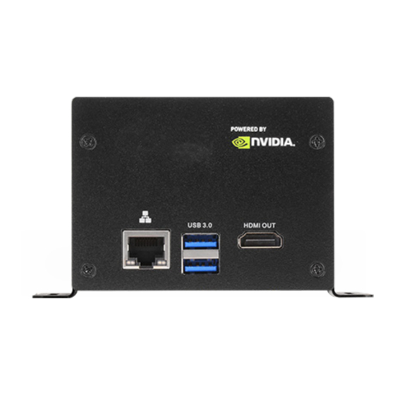
Chapter 2 HARDWARE INSTALLATION Chapter 2 - Hardware Installation X Overview Front Panel (4 x LAN, 2 x USB) RECOVERY USB 3.0 DC-in POWER SYSTEM Light and Power Light HDMI OUT User's Manual | EC102-XNX... - Page 8 Chapter 2 HARDWARE INSTALLATION MicroSD Card User's Manual | EC102-XNX...
-
Page 9: Block Diagram
USB3.0 TYPE A NVIDIA Jetson Nano / USB1 Jetson Xavier NX MIPI 4LAN CSI4 with OTG micro USB0 USB 2.0 micro SDMMC SD card HDMI 2.0 HDMI DP1/HDMI type A UART1 MINI54 20pin I/O GPIOS/Control Expansion User's Manual | EC102-XNX... -
Page 10: Board Layout
20 Pin GPIO expansion SOCKET_DDR4 HDMI output connector RTC battery for module Fan Power Connector USB 3.1 Gen 1 Type Micro SD Card Fan PWM controller / Auto Power on MIPI camera module connector RECOVERY button POWER on button User's Manual | EC102-XNX... -
Page 11: System Memory
Retention Notch Notch DDR3 SO-DIMM The system board supports the following memory interface. Single Channel (SC) Data will be accessed in chunks of 64 bits from the memory channels. Retention Clip Socket Top View 4 5 ° User's Manual | EC102-XNX... - Page 12 Inspect that the clip sits in the notch. If not, please pull the clips outward, release and remove the Step 3 card, and mount it again. User's Manual | EC102-XNX...
-
Page 13: I/O Ports
The HDMI port which carries both digital audio and video signals is used to connect a LCD monitor or digital TV that has the HDMI port. USB allows data exchange between your computer and a wide range of simultaneously acces- sible external Plug and Play peripherals. User's Manual | EC102-XNX... -
Page 14: Rj45 Lan Ports
HARDWARE INSTALLATION I/O Ports I/O Ports RJ45 LAN Ports Micro SD Card Slot The LAN port allows the system board to connect to a local area network by means of a net- For MicroSD Card. work hub. User's Manual | EC102-XNX... -
Page 15: Battery
„ Fan Pin Assignment • Replace only with the same or equivalent type recommended by the manufacturer. • Dispose of used batteries according to local ordinances. Define „ Battery Pin Assignment Power +5V Define FAN_TACH 3V Power FAN_PWM User's Manual | EC102-XNX... -
Page 16: Expansion Slots - Mipi Camera Module Connector
Expansion Slots - MIPI camera module connector DDR4_1 SODIMM „ Pin Assignment Define Define +5V MIPI +5V MIPI CSI4_D2_P +1V8 CSI4_D3_N +3.3V MIPI +3.3V MIPI +3.3V MIPI CSI4_D0_P MIPI4_PWDN CSI4_D0_N CSI4_I2C_SDA CSI4_I2C_SCL CSI4_CLK_P CSI_CLK_N CSI4_D1_N CSI4_D2_P CAM4_MCLK CSI4_D3_P User's Manual | EC102-XNX... -
Page 17: Expansion Slots - 20 Pin Gpio Expansion
This port is for OTG programming, any USB standard Micro type interface cable or device fits the port. +3V3 I2C1_SDA UART2_TXD_3V3 Debug Console /dev/i2c-1 /dev/ttyS0 I2C1_SCL UART2_RXD_3V3 I2C0_SDA /dev/i2c-0 I2C0_SCL SPI1_SCK gpio14 I2S0_SCLK gpio79 SPI1_MISO gpio13 I2S0_DOUT gpio78 SPI1_MOSI gpio12 I2S0_DIN gpio77 SPI1_CS0 gpio15 I2S0_FS gpio76 SPI1_CS1 gpio232 User's Manual | EC102-XNX... -
Page 18: Force Recovery
Chapter 2 HARDWARE INSTALLATION I/O Ports I/O Ports Force recovery Power control button This button is for force recovery. This button is for Power ON/OFF the machine. User's Manual | EC102-XNX... -
Page 19: Fan Pwm Controller / Auto Power On
I/O Ports Fan PWM controller / Auto Power on „ Switch Switch Define (OFF) Fan PWM controller Fan always on Auto power on Auto power on disabled Test mode off Test mode on (for the factory use) User's Manual | EC102-XNX... -
Page 20: Chapter 3 - First-Time Use & Maintenance
5. NVIDIA® Jetson Nano/Xavier NX will show up on the USB list of the host system as a new NVIDIA target device. 6. After the system software is updated successfully, please ensure to power off the system. A clean power-on will then revert OTG port back to the host mode. User's Manual | EC102-XNX...
Need help?
Do you have a question about the EC102-XNX and is the answer not in the manual?
Questions and answers