DFI EC700-BT User Manual
Fanless embedded system
Hide thumbs
Also See for EC700-BT:
- Installation manual (4 pages) ,
- Quick installation manual (4 pages)

Related Manuals for DFI EC700-BT


Summary of Contents for DFI EC700-BT
- Page 1 EC700-BT Fanless Embedded System User’s Manual A33130546 Chapter 1 Introduction www.dfi .com...
-
Page 2: Copyright
Copyright FCC and DOC Statement on Class B This publication contains information that is protected by copyright. No part of it may be re- This equipment has been tested and found to comply with the limits for a Class B digital produced in any form or by any means or used to make any transformation/adaptation without device, pursuant to Part 15 of the FCC rules. -
Page 3: Table Of Contents
Key Features ....................6 Chassis Intrusion Connector ............... 28 Specifications ....................7 Expansion Slots ..................29 Getting the Know the EC700-BT ............8 Standby Power LED ................... 29 Mechanical Dimensions ................9 Battery ..................... 30 Chapter 2 - Getting Started .............. -
Page 4: About This Manual
About this Manual Static Electricity Precautions An electronic file of this manual is included in the CD. To view the user’s manual in the CD, in- It is quite easy to inadvertently damage your PC, system board, components or devices even sert the CD into a CD-ROM drive. -
Page 5: Safety Precautions
• Unplug the power cord before removing the system chassis cover for installation or servic- ing. After installation or servicing, cover the system chassis before plugging the power cord. • 1 EC700-BT system unit • Mounting screws for SATA drive •... -
Page 6: Chapter 1 - Introduction
Chapter 1 Chapter 1 - Introduction Overview Key Features Model Name EC700-BT Processor ® ® ® Intel Atom /Intel Celeron processors Memory 4GB/2GB DDR3L onboard 2 LAN ports 4 COM ports Display 1 HDMI, 1 VGA or 1 DVI-I* (optional) 1 Type A USB 3.0 port at the front panel;... -
Page 7: Specifications
Chapter 1 Specifications • 4 DB-9 ports Processor System Intel ® Atom /Intel ® Celeron ® processors • - 3 DB-9 ports support RS232/422/485 COM port ® - Intel Atom E3845, Quad Core, 2M Cache, 1.91GHz, 10W - 1 DB-9 port supports RS232/422/485 COM or 8-bit DIO ®... -
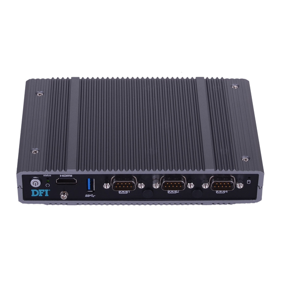
Page 8: Getting The Know The Ec700-Bt
Chapter 1 Getting to Know the EC700-BT Front View Rear View Status COM 1 COM 4 / 8-bit DIO COM 2 Power HDMI LAN 1/2 HDD LED COM 3 USB 2.0 USB 3.0 DC-in Antenna Antenna Antenna Hole Hole Hole... -
Page 9: Mechanical Dimensions
Chapter 1 Mechanical Dimensions Chassis Dimension Motherboard Dimension 113.4 102.93 99.26 105.85 103.35 21.8 Left View Right View 19.8 11.45 11.8 9.65 Front View BT253 Chapter 1 Introduction www.dfi .com... -
Page 10: Chapter 2 - Getting Started
Chapter 2 Chapter 2 - Getting Started Preparing the System Before you start using the system, you need the following items: • SATA hard drive • AC power adapter • CD-ROM drive (for installing software/drivers) • Screwdriver Installing Devices The following are devices that can be installed in the system. •... -
Page 11: Chapter 3 - Installing Devices
Chapter 3 Chapter 3 - Installing Devices 5. The 3 Mini PCIe slots, the microSD socket and the HDD bracket are readily accessible after removing the bottom side of the chassis cover. Removing the Chassis Cover 1. Make sure the system and all other peripheral devices connected to it has been powered-off. Full size Mini PCIe slot: PCIe, USB, and 3G signals 2. -
Page 12: Installing A 2.5" Sata Drive
Chapter 3 Installing a 2.5” SATA Drive 1. Locate the SATA drive bay on the system board. Unplug the SATA power and data cable, and remove the 4 mounting screws that secure the drive bay to the system board. SATA data cable Mounting Screw SATA power cable SATA drive bay... -
Page 13: Installing A Sim Card
Chapter 3 Installing a SIM Card 3. Place the SATA drive bay into the chassis. Secure the SATA drive bay with the mounting screws you removed in step 1. And connect the SATA data cable and SATA power cable to the connectors on the system board. -
Page 14: Installing A Mini Pcie And/Or Msata Card
Chapter 3 Installing a Mini PCIe and/or mSATA card 3. Grasping the Mini PCIe card by its edges, align the card into the slot at an approximately 30 degrees angle. Apply fi rm even pressure to each end of the card until it slips down into the Installing the Mini PCIe Card slot. - Page 15 Chapter 3 Installing the mSATA Card 3. Grasping the mSATA card by its edges, align the card into the slot at an approximately 30 degrees angle. Apply fi rm even pressure to each end of the card until it slips down into the slot.
-
Page 16: Chapter 4 - Jumper Settings
Chapter 4 Chapter 4 - Jumper Settings Auto Power-on Select Clear CMOS Data JP24 1-2 On: Normal (default) 2-3 On: 1-2 On: Clear CMOS Data Power-on via power button (default) JP25 2-3 On: Power-on via AC power If you encounter the following, a) CMOS data becomes corrupted. -
Page 17: Usb Power Select
Chapter 4 USB Power Select Panel Power Select 5 3 1 6 4 2 1-2 On: +12V 5 3 1 6 4 2 USB 1-2 1-2 On: USB 0 (JP6) +5V_standby 3-4 On:+5V (JP5) 1-2 On: (default) +5V_standby JP23 5 3 1 (default) 2-3 On: +5V 6 4 2... -
Page 18: Backlight Power Select
Chapter 4 Backlight Power Select Dimming Mode Select 1-2 On: Voltage Mode 1-2 On: +5V 2-3 On: +3.3V (default) 2-3 On: PWM Mode (default) JP4 allows you to select the mode for the lightness control of the LVDS panel. JP3 is used to select the power level of backlight brightness control: +5V or +3.3V. Important: Important: Before powering-on the system, make sure that the power settings of JP3 match the... -
Page 19: Digital I/O Power Select
Chapter 4 Digital I/O Power Select Digital I/O Output State JP20 (DIO 0-3) JP17 JP18 (DIO 4-7) 1-2 On: 1-2 On: GND (default) +5V_standby 2-3 On: 2-3 On: +5V +5V or +5V_standby (default) JP17 is used to select the power of DIO (Digital I/O) signal. Based on the power level of DIO (Digital I/O) selected on JP17, JP20 (DIO pin 0-3) and JP18 (DIO pin 4-7) are used to select the state of DIO output: pull high or pull low. -
Page 20: Lcd/Inverter Power Select
Chapter 4 LCD/Inverter Power Select COM 4/DIO Select JP22 JP21 1-2, 4-5, 7-8, 10-11 On: COM 4 (default) 2-3, 5-6, 8-9, 11-12 On: 1-2 On: +12V (default) 2-3 On: +5V JP2 is used to select the power level of the LCD/inverter power connector. The system board uses JP21 and JP22 to select between RS232/422/485 COM 4 or 8-bit DIO at the rear panel. -
Page 21: Chapter 5 - Ports And Connectors
Chapter 5 Chapter 5 - Ports and Connectors Front Panel I/O Ports Rear Panel I/O Ports Status LED COM 4/8-bit DIO COM 1 COM 2 HDMI DC-in Power USB 2.0 USB 3.0 COM 3 Reset HDD LED Antenna Antenna LAN 1 LAN 2 Hole Hole Antenna... -
Page 22: Usb Ports
Chapter 5 USB Ports Driver Installation You may need to install the proper drivers in your operating system to use the USB device. Refer to chapter 4 for more information. Wake-On-USB Keyboard/Mouse The Wake-On-USB Keyboard/Mouse function allows you to use a USB keyboard or USB mouse to wake up a system from the S3 (STR - Suspend To RAM) state. -
Page 23: Com (Serial) Ports
Chapter 5 COM (Serial) Ports Important: When installing Windows 7, only native USB 2.0 devices (USB port 0 to USB port 3) can operate under DOS mode. Please refer to the following tables for more infomation on the type of USB ports. Table 1. -
Page 24: Graphics Interfaces
Chapter 5 Graphics Interfaces COM 1/COM 2 /COM 3 The display ports consist of the following: • 1 HDMI port 1 2 3 4 5 1 2 3 4 5 1 2 3 4 5 • 1 VGA port 6 7 8 9 6 7 8 9 6 7 8 9 RS232... -
Page 25: 9~36V Dc-In
Chapter 5 9~36V DC-in RJ45 LAN Ports LAN 1 LAN 2 DC-in Features This jack provides maximum of 120W power and is considered a low power solution. Connect a DC power cord to this jack. Use a power adapter within 9~36V DC output voltage. (We only •... -
Page 26: I/O Connectors
Chapter 5 I/O Connectors Cooling Fan Connector Serial ATA Connector Serial ATA Power Connector SATA 2.0 3Gb/s SATA 1 SATA Power System Fan The fan connector is used to connect the cooling fan. The cooling fan will provide adequate airflow throughout the chassis to prevent overheating the CPU and system board components. Features BIOS Setting •... -
Page 27: Lvds Lcd Panel With Power Connector
Configure the LCD panel in the Advanced/Chipset Features submenu of the BIOS. Refer to chapter 7 for more information. Backlight Power Panel Power Note: DFI board's LVDS connector: Hirose DF13-40DP-1.25V(91)/40P/1.25mm; cable side connector: Hirose DF13-40DS-1.25C. Chapter 5 Ports and Connectors www.dfi .com... -
Page 28: Mic-In Connector
Chapter 5 Mic-in Connector Chassis Intrusion Connector Chassis Intrusion Ground Signal Mic-in The board supports the chassis intrusion detection function. Connect the chassis intrusion sensor cable from the chassis to this connector. When the system’s power is on and a chassis intrusion occurred, an alarm will sound. -
Page 29: Expansion Slots
Chapter 5 Expansion Slots Standby Power LED Mini PCIe for USB, PCIe and LPC signals microSD socket (optional) Standby Power LED Mini PCIe for mSATA SIM slot This LED will blink when the system is in the standby mode. It indicates that there is power Mini PCIe for on the system board. -
Page 30: Battery
Chapter 5 Battery Battery Battery Ground Connect to the battery connector Battery The lithium ion battery powers the real-time clock and CMOS memory. It is an auxiliary source of power when the main power is shut off. Safety Measures • Danger of explosion if battery incorrectly replaced. •... -
Page 31: Chapter 6 - Mounting Options
Chapter 6 Chapter 6 - Mounting Options 2. At the top side of the system, use the provided mounting screws to secure the wallmount brackets on each side of the system. Wall Mount The wall mount kit includes the following: Mounting screw •... -
Page 32: Vesa Mount
• 2 VESA mount bracket B • Bracket screws Mounting Screw EC700-BT VESA bracket A VESA bracket B 1. Prior to installing the VESA mount bracket A, make sure you have already installed the VESA mount bracket B. 2. Used the provided mounting screws to secure the VESA bracket A in place. -
Page 33: Din Rail Mount
• 1 bracket • Bracket screws Bracket EC700-BT 1. Turn the system to the top side and bottom side and locate the mounting screw. Remove EC700-BT these screws and then put them in a safe place for later use. Bracket Mounting Screw 3. - Page 34 Chapter 6 4. Align the mounting holes of the bracket in the system and the mounting holes on the DIN rail bracket, and then use the provided mounting screws to secure the bracket in place. DIN Rail bracket Mounting Screw Bracket Chapter 6 Mounting Options www.dfi...
-
Page 35: Chapter 7 - Bios Setup
Chapter 7 Chapter 7 - BIOS Setup Legends Overview Keys Function The BIOS is a program that takes care of the basic level of communication between the CPU and peripherals. It contains codes for various advanced features found in this system board. Moves the highlight left or right to select a menu. -
Page 36: Ami Bios Setup Utility
Chapter 7 AMI BIOS Setup Utility Advanced Main The Advanced menu allows you to configure your system for basic operation. Some entries are defaults required by the system board, while others, if enabled, will improve the performance of your system or let you set some features according to your preference. The Main menu is the first screen that you will see when you enter the BIOS Setup Utility. - Page 37 Chapter 7 Trusted Computing NCT6106D Super IO Configuration This section configures settings relevant to Trusted Computing innovations. This section is used to configure the parameters of the system super IO chip. Aptio Setup Utility - Copyright (C) 2013 American Megatrends, Inc. Aptio Setup Utility - Copyright (C) 2013 American Megatrends, Inc.
- Page 38 Chapter 7 Serial Port 1 Configuration to Serial Port 6 Configuration Sets the parameters of serial port 1 (COM A) and serial port 6 (COM F). Aptio Setup Utility - Copyright (C) 2013 American Megatrends, Inc. Aptio Setup Utility - Copyright (C) 2013 American Megatrends, Inc. Advanced Advanced Serial Port 1 Confi...
- Page 39 Chapter 7 Serial Port Aptio Setup Utility - Copyright (C) 2013 American Megatrends, Inc. Advanced Enable or disable the serial COM port. Serial Port 5 Confi guration Enable or Disable Serial Port (COM) Change Settings Serial Port [Enabled] IO=2F0h; IRQ=10; Device Settings Select the IO/IRQ settings for the super I/O device.
- Page 40 Chapter 7 HW Monitor CPU Configuration This section is used to monitor the hardware status. This section is used to configure the CPU. It will also display the detected CPU information. Aptio Setup Utility - Copyright (C) 2013 American Megatrends, Inc. Aptio Setup Utility - Copyright (C) 2013 American Megatrends, Inc.
- Page 41 Chapter 7 SATA Configuration Network Stack Configuration This section is used to enable or disable SATA devices. This section is used to enable or disable network stack settings. Aptio Setup Utility - Copyright (C) 2013 American Megatrends, Inc. Aptio Setup Utility - Copyright (C) 2013 American Megatrends, Inc. Advanced Advanced Network Stack...
- Page 42 Chapter 7 Ipv4 PXE Support CSM Configuration This section configures the CSM settings. When enabled, Ipv4 PXE boot supports. When disabled, Ipv4 PXE boot option will not be created. Aptio Setup Utility - Copyright (C) 2013 American Megatrends, Inc. Ipv6 PXE Support Advanced When enabled, Ipv6 PXE boot supports.
- Page 43 Chapter 7 USB Configuration Important: When installing Windows 7, only native USB 2.0 devices (USB port 0 to USB port 3) This section is used to configure the parameters of USB device. can operate under DOS mode. Please refer to the following tables for more infomation on the type of USB ports.
- Page 44 Chapter 7 Security Configuration Intel(R) I210 Gigabit Network Connection - 00:01:29:51... This section only displays the setting relevant to the Intel(R) Anti-Theft Technology. This section is used to configure the parameters of Gigabit Ethernet device. Aptio Setup Utility - Copyright (C) 2013 American Megatrends, Inc. Aptio Setup Utility - Copyright (C) 2013 American Megatrends, Inc.
- Page 45 Chapter 7 NIC Configuration Intel(R) I210 Gigabit Network Connection - 00:01:29:51... This field is used to configure the network device. This section is used to configure the parameters of Gigabit Ethernet device. Aptio Setup Utility - Copyright (C) 2013 American Megatrends, Inc. Aptio Setup Utility - Copyright (C) 2013 American Megatrends, Inc.
- Page 46 Chapter 7 Chipset NIC Configuration This field is used to configure the network device. This section configures relevant chipset functions. Aptio Setup Utility - Copyright (C) 2013 American Megatrends, Inc. Aptio Setup Utility - Copyright (C) 2013 American Megatrends, Inc. Advanced Main Advanced...
- Page 47 Chapter 7 North Bridge Intel IGD Configuration This section configures the North bridge parameters. Aptio Setup Utility - Copyright (C) 2013 American Megatrends, Inc. Chipset Aptio Setup Utility - Copyright (C) 2013 American Megatrends, Inc. IGD LCD Control Settings Integrated Graphics [Enabled] Chipset Primary Display...
- Page 48 Chapter 7 Bus Type Memory Configuration Select the bus type for the flat panel: single LVDS or dual LVDS. Aptio Setup Utility - Copyright (C) 2013 American Megatrends, Inc. Chipset Data Type Memory Information Select the data type for the flat panel: 18-bits, 24-bits (VESA) or 24-bits (JEIDA). Total Memory 4096 MB (LPDDR3) Panel Type...
- Page 49 Chapter 7 South Bridge USB Configuration This field is used to configure the parameters of the South Bridge. Aptio Setup Utility - Copyright (C) 2013 American Megatrends, Inc. Chipset Aptio Setup Utility - Copyright (C) 2013 American Megatrends, Inc. Chipset USB Confi...
- Page 50 Chapter 7 Security PCI Express Configuration This section configues settings relevant to PCI Express devices. Aptio Setup Utility - Copyright (C) 2013 American Megatrends, Inc. Aptio Setup Utility - Copyright (C) 2013 American Megatrends, Inc. Main Advanced Chipset Security Boot Save &...
- Page 51 Chapter 7 Boot Save & Exit Aptio Setup Utility - Copyright (C) 2013 American Megatrends, Inc. Aptio Setup Utility - Copyright (C) 2013 American Megatrends, Inc. Main Advanced Chipset Security Boot Save & Exit Main Advanced Chipset Security Boot Save & Exit Save Changes and Reset Reset the system after Number of seconds to...
-
Page 52: Updating The Bios
Chapter 7 Updating the BIOS Notice: BIOS SPI ROM To update the BIOS, you will need the new BIOS file and a flash utility, AFUDOS. 1. The Intel Management Engine has already been integrated into this system board. Due to ®... -
Page 53: Chapter 8 - Supported Software
Chapter 8 Chapter 8 - Supported Software Auto Run Page (For Windows 7) The CD that came with the system board contains drivers, utilities and software applications required to enhance the performance of the system board. Insert the CD into a CD-ROM drive. The autorun screen (Mainboard Utility CD) will appear. If after inserting the CD, “Autorun”... - Page 54 Chapter 8 Intel Chipset Software Installation Utility 3. Go through the readme docu- ment for more installation tips then click Next. The Intel Chipset Device Software is used for updating Windows INF files so that the Intel ® chipset can be recognized and configured properly in the system. To install the utility, click “Intel Chipset Software Installation Utility”...
- Page 55 Chapter 8 Intel HD Graphics Drivers 3. Go through the readme docu- ment for system requirements and installation tips then click To install the driver, click “Intel HD Graphics Drivers” on the main menu. Next. 1. Setup is now ready to install the graphics driver.
- Page 56 Chapter 8 Intel LAN Drivers 4. Click Install to begin the installation. To install the driver, click “Intel LAN Drivers” on the main menu. 1. Setup is ready to install the driver. Click Next. 5. After completing installa- tion, click Finish. 2.
- Page 57 Chapter 8 Kernel Mode Driver Framework (For Windows 7 only) Intel Trusted Execution Engine Driver To install the driver, click “Kernel Mode Driver Framework” on the main menu. To install the driver, click “Intel Trusted Execution Engine Driver” on the main menu. 1.
- Page 58 Chapter 8 Realtek Audio Drivers 3. The step displays the installing status in the progress. To install the driver, click “Realtek Audio Drivers” on the main menu 1. Setup is now ready to install the audio driver. Click Next. 2. Follow the remainder of the steps on the screen;...
- Page 59 Chapter 8 HW Utility 3. Click Install to begin the installation. HW Utility provides information about the board, HW Health, Watchdog, DIO, and Backlight. To access the utility, click “HW Utility” on the main menu. Note: If you are using Windows 7, you need to access the operating system as an administrator to be able to install the utility.
- Page 60 Chapter 8 The HW Utility icon will appear on the desktop. Double-click the icon to open the utility. Information HW Health Set HW Health WatchDog Chapter 8 Supported Software www.dfi .com...
- Page 61 Chapter 8 Infineon TPM Driver and Tool (option) To install the driver, click “Infineon TPM driver and tool (option)” on the main menu. 1. The setup program is preparing to install the driver. 2. The setup program is now ready to install the utility.
- Page 62 Chapter 8 4. Enter the necessary information 7. TPM requires installing the Micro- and then click Next. soft Visual C++ package prior to installing the utility. Click Install. 5. Select a setup type and then click 8. The setup program is currently Next.
- Page 63 Chapter 8 Intel USB 3.0 Drivers (For Windows 7 Only) 10. Click “Yes“ to restart your system. To install the driver, click “Intel USB 3.0 Driver” on the main menu. 1. Setup is ready to install the driver. Click Next. 2.
- Page 64 Chapter 8 Adobe Acrobat Reader 9.3 3. Go through the readme docu- ment for more installation tips then click Next. To install the reader, click “Adobe Acrobat Reader 9.3” on the main menu. 1. Click Next to install or click Change Destination Folder to select another folder.
-
Page 65: Chapter 9 - Digital I/O Programming Guide
Chapter 9 Chapter 9 - Digital I/O Programming Guide The Configuration Register (register 3) configures the direction of the I/O pins. If a bit in this register is set to 1, the corresponding port pin is enabled as an input with a high-impedence Register Description output driver. - Page 66 Chapter 9 Function Description GPIO Output Process I2CWriteByte(SlaveAddr, SubAddr, Data): #defi ne SLAVE_ADDR 0x42 Write a Byte data to a specified I2C Device. #defi ne INPUT_PORT 0x00 #defi ne OUTPUT_PORT 0x01 I2CReadByte(SlaveAddr, SubAddr, *Data): 0x02 #defi ne INVERSION_PORT Read a Byte data from a specified I2C Device. 0x03 #defi...
-
Page 67: Appendix A - Watchdog Sample Code
Appendix A Appendix A - Watchdog Sample Code ;Software programming example: ;--------------------------------------------- ;(1) Enter Super IO Confi guration mode ;--------------------------------------------- DX,2EH AL,87H DX,AL DX,AL ;------------------------------------------------------------------------------------------- ;(2) Confi guration Logical Device 7, register CRF5/CRF6 (WDT Control /WDT timer) ;------------------------------------------------------------------------------------------- DX,2EH AL,07H ;Ready to Program Logical Device DX,AL DX,2FH... -
Page 68: Appendix B - System Error Message
Appendix B Appendix B - System Error Message Hard Disk(s) fail (20) When the BIOS encounters an error that requires the user to correct something, either a beep HDD initialization error. code will sound or a message will be displayed in a box in the middle of the screen and the message, PRESS F1 TO CONTINUE, CTRL-ALT-ESC or DEL TO ENTER SETUP, will be shown in Hard Disk(s) fail (10) the information box at the bottom. -
Page 69: Appendix C - Troubleshooting Checklist
Appendix C Appendix C - Troubleshooting Checklist The picture seems to be constantly moving. Troubleshooting Checklist 1. The monitor has lost its vertical sync. Adjust the monitor’s vertical sync. 2. Move away any objects, such as another monitor or fan, that may be creating a magnetic This chapter of the manual is designed to help you with problems that you may encounter field around the display. - Page 70 Appendix C Hard Drive System Board 1. Make sure the add-in card is seated securely in the expansion slot. If the add-in card is Hard disk failure. loose, power off the system, re-install the card and power up the system. 1.
Need help?
Do you have a question about the EC700-BT and is the answer not in the manual?
Questions and answers