
Related Manuals for DFI EC900-FS6


Summary of Contents for DFI EC900-FS6
- Page 1 EC900-FS6 Fanless Embedded System User’s Manual A48300809 Chapter 1 Introduction...
- Page 2 Copyright FCC and DOC Statement on Class A This publication contains information that is protected by copyright. No part of it may be re- This equipment has been tested and found to comply with the limits for a Class B digital produced in any form or by any means or used to make any transformation/adaptation without device, pursuant to Part 15 of the FCC rules.
-
Page 3: Table Of Contents
Chapter 7 - Supported Software ....23 Overview .................6 Key Features ................6 Specifications ................7 Getting to Know the EC900-FS6 ..........8 Mechanical Dimensions ............9 Chapter 2 - Getting Started ...... 10 Chapter 3 - Installing Devices ....11 Removing the Chassis Cover ........... 11 Chapter 4 - Jumper Settings ..... -
Page 4: About This Manual
About this Manual Static Electricity Precautions An electronic file of this manual can be obtained from the DFI website at www.dfi.com. To It is quite easy to inadvertently damage your PC, system board, components or devices even download the user’s manual from our website, please go to Support > Download Center. On before installing them in your system unit. -
Page 5: Safety Precautions
• Unplug the power cord before removing the system chassis cover for installation or servic- ing. After installation or servicing, cover the system chassis before plugging the power cord. • One EC900-FS6 system unit • One Quick Installation Guide • Danger of explosion if battery incorrectly replaced. -
Page 6: Chapter 1 - Introduction
Chapter 1 Chapter 1 - Introduction Overview Key Features Model Name EC900-FS6 Processor NXP i.MX6 Series Processor NXP i.MX6 Cortex-A9 Dual Lite, 1.0GHz Two LAN ports Front View Two serial port: 2-wire RS485 4-wire RS422 Display One HDMI Two USB 2.0 Type A ports... -
Page 7: Specifications
Chapter 1 Specifications Processor NXP i.MX6 Series Processor System NXP i.MX6 Cortex-A9 Dual Lite, 1.0GHz Memory • 1GB/2GB SDRAM Memory Down Single Channel DDR3L 1600MHz Graphics • Display interface HDMI: resolution up to 1920x1080 @ 60 Hz Vibration • Operating: Random 5~500Hz, IEC68-2-64 (3G) Storage/ •... -
Page 8: Getting To Know The Ec900-Fs6
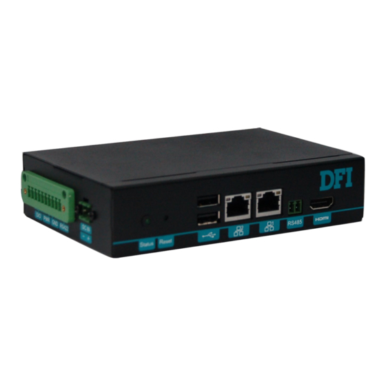
Chapter 1 Getting to Know the EC900-FS6 Front View Rear View Status LED (green) LAN 2 LAN 1 HDMI Digital IO RS422 (4-pin) USB 2.0 Reset (4-pin) COM (RS485) DC-in ̶ + Power (1-pin) Ground (1-pin) Status LED (blue) DC-in Connector DC 9~36V power input via a terminal block connector. -
Page 9: Mechanical Dimensions
Chapter 1 Mechanical Dimensions Chassis Dimension Left View Bottom View Top View Front View Right View Chapter 1 Introduction... -
Page 10: Chapter 2 - Getting Started
Chapter 2 Chapter 2 - Getting Started Preparing the System Before you start using the system, you need the following items: • AC power cord • Screwdriver Installing Devices The following devices can be installed in the system. • Mini PCIe card •... -
Page 11: Chapter 3 - Installing Devices
Chapter 3 Chapter 3 - Installing Devices Removing the Chassis Cover Lift the cover to open the system. The Mini PCIe socket is readily accessible after removing the bottom cover. Please observe the following guidelines and follow the procedure to open the system. Make sure the system and all other peripheral devices connected to it have been powered off. - Page 12 Chapter 3 Installing a Mini PCIe Card The system board is equipped with one Mini PCIe slot that supports both PCIe and USB signals. Grasp the Mini PCIe card by its edges and align the notch of the PCIe card with the key in the connector on the system board.
-
Page 13: Chapter 4 - Jumper Settings
Chapter 4 Chapter 4 - Jumper Settings Boot Mode Select Front COM 3 Panel eMMC LVDS LCD Panel i.MX6 Cortex-A9 1 2 3 4 5 6 7 8 DDR3L DDR3L 1 2 3 4 5 6 7 8 To select the boot mode and boot device, please use finger switch SW5. Boot Mode Select Boot from the fuses 7 Off, 8 Off... -
Page 14: Chapter 5 - Ports And Connectors
Chapter 5 Chapter 5 - Ports and Connectors Panel I/O Ports Reset RS485 HDMI LAN 2 LAN 1 DC-IN DI/DO USB 2.0 RS422 Status LED (green) The left panel I/O port consists of the following ports: The front panel I/O consists of the following ports: •... -
Page 15: Rj45 Lan Ports
Chapter 5 RJ45 LAN Ports 9~36V DC-in LAN 2 LAN 1 Features • 2 LAN ports built on Atheros Ethernet PHY AR8033-AL1B (10/100/1000Mbps) and Microchip This 2-pin terminal block is considered a low power solution. This connector is wired as an USB to Ethernet Controller LAN7500-ABZJ (10/100/1000Mbps) external DC-in connector and reset button for power control. -
Page 16: Usb Ports
Chapter 5 USB Ports Serial Port COM 1 USB 2.0 The USB 2.0 ports (USB 1-3) and OTG connector are used for USB communication. In addi- The COM 1 port provides 2-wire RS485 communication with support for auto flow control. tion, the USB OTG allows the board and the devices connected to it to switch back and forth between the roles of host and device. -
Page 17: Graphics Interface
Chapter 5 Graphics Interface I/O Connectors The display port consists of the following: Digital I/O Connector • 1 HDMI port Digital I/O 1 2 3 4 5 6 External Connector HDMI The internal digital I/O connector supports 8-bit digital input/output with power connectivity to provide monitoring and control function of the devices connected to the DIO port. -
Page 18: Serial Port
Chapter 5 Serial Port External RS-422 TX_B COM 3: RS232/422/485 TX_A 1 2 3 4 External Connector RX_A Front COM 3 Panel RX_B eMMC LVDS LCD Panel i.MX6 Cortex-A9 1 2 3 4 5 6 7 8 DDR3L DDR3L COM 3 can be used for RS232, RS422 or RS485 communication. And the RS485 supports auto flow control. -
Page 19: Expansion Slots
Chapter 5 Expansion Slots C Connector Front COM 3 Front COM 3 Panel Panel JTAG DC-in USB 2.0 Panel Backlight/SATA Power USB 1-2 LAN 2 eMMC eMMC Debug LED USB 2.0 USB 3 LAN 1 USB OTG LVDS LCD Panel LVDS LCD Panel i.MX6 i.MX6... -
Page 20: Front Panel Connector
Chapter 5 Front Panel Connector Battery Front Panel JTAG Front DC-in COM 3 Panel USB 2.0 Panel Backlight/SATA Power USB 1-2 LAN 2 eMMC Debug LED USB 2.0 USB 3 LAN 1 USB OTG LVDS LCD Panel COM 1 i.MX6 Cortex-A9 1 2 3 4 5 6 7 8 HDMI... -
Page 21: Debug Connectors
Chapter 5 Debug Connectors JTAG JTAG DC-in USB 2.0 Panel Backlight/SATA Power USB 1-2 LAN 2 Debug LED USB 2.0 USB 3 LAN 1 USB OTG COM 1 HDMI DDR3L DDR3L Mini PCIe Debug Battery Debug The JTAG and debug connectors are used for debugging purposes. Debug Connector JTAG Connector Pin Name... -
Page 22: Chapter 6 - Mounting Options
Chapter 6 Chapter 6 - Mounting Options DIN-rail Mount The system features DIN-rail mount chassis that facilitates fast installation of the EC900-FS6 to a DIN rail. The DIN Rail mount kit includes the following: • Din-rail mount bracket • 2 screws Use the provided mounting screws to attach the din-rail mount bracket to the rear side of the device. -
Page 23: Chapter 7 - Supported Software
2. Connect your PC and the system using a Micro USB cable. Pins 1, 2, 5, 6, 7 ON 3. Power on the system. 8. Click "Stop" to stop or to halt the process. Micro USB Cable Important: The adapter output voltage is 9~36V. Chapter 7 Supported Software www.dfi.com... - Page 24 10. Power on the device again to reboot it into the system. Boot Mode/Device Select Connect your PC and the system using a Micro USB cable. (SW5) Pins 1, 2, 5, 6, 7 ON Important: The adapter output voltage is 9~36V. Micro USB Cable Chapter 7 Supported Software www.dfi.com...
- Page 25 Wait until the completion of the burning process. 10. Power on the device again to reboot it into the system. 8. Click "Stop" to stop or to halt the process. Chapter 7 Supported Software www.dfi.com...
- Page 26 All library, utility and Android apk should Support Android AOSP launcher support (*). Support Android ADB shell Source code package (support by request) Android Support Android APK install AP/API Support I C, Watchdog and GPIO Provide support console for i.MX6 platform. Chapter 7 Supported Software www.dfi.com...
- Page 27 Android Support Component Support Status This feature depends on the NXP’s support. Support Loopback test, BR 115200 (need DFI Linux user space utility) UART1 - RS485 Component Support Status Support Loopback test, BR 115200 (need DFI Linux user space utility) UART2 - RS422 5.1.1...
- Page 28 (4) Support Android Airplane mode to disable WiFi function (5) Not support STA mode and Soft AP mode enable at the same time Support Loopback test, BR 115200 by DFI Android UART demo APP (6) Not support other WiFi modes, i.e. Wi-Fi Direct, Miracast, Wi-Fi...
- Page 29 AOSP Audio module test in the future 15. NXP Audio Route (*): function not ready, preload for Audio module test in the future. 16. NXP Ethernet (*): Ethernet settings APP. 17. Open-source Simple Explorer: File Explorer APP Chapter 7 Supported Software www.dfi.com...
Need help?
Do you have a question about the EC900-FS6 and is the answer not in the manual?
Questions and answers
Best way to determine if a device is hooked up to wire connection or wifi remotely
You can determine if a DFI EC900-FS6 device is connected via a wired connection or Wi-Fi by checking its network status. The device does not support STA mode and Soft AP mode at the same time, and when a wired LAN connection is plugged in, STA mode (Wi-Fi) will disconnect automatically due to Android network framework limitations.
To check the connection remotely, you can:
1. Use the "busybox lspci" console command to check for the presence of a PCIe Wi-Fi card.
2. Verify the network connection status through the Android UI if available.
3. Check if the Soft AP mode is enabled, which indicates the device is using Wi-Fi.
If the device is in STA mode and loses connection when a wired LAN is plugged in, it confirms that the device is prioritizing the wired connection over Wi-Fi.
This answer is automatically generated