
Related Manuals for DFI EC531-HD


Summary of Contents for DFI EC531-HD
- Page 1 EC531/EC532-HD/DL Modular-Designed Embedded System User’s Manual A-392-M-2008 Chapter 1 Introduction www.dfi.com...
-
Page 2: Copyright
Product names or trademarks appearing in this manual are for identification purpose only and Shielded interface cables must be used in order to comply with the emission limits. are the properties of the respective owners. Chapter 1 Introduction www.dfi.com... -
Page 3: Table Of Contents
Mini PCIe Power Select ................26 Appendix B - System Error Message ........... 94 Jumper Setting - I/O Board Appendix C - Troubleshooting ..............95 USB Power Select ..................26 COM 7/COM 8 RS232/422/485 Select ..........27 Chapter 1 Introduction www.dfi.com... -
Page 4: About This Manual
About this Manual Static Electricity Precautions An electronic file of this manual can be obtained from the DFI website at www.dfi.com. It is quite easy to inadvertently damage your PC, system board, components or devices even To download the user’s manual from our website, please go to “Support” > “Download Center.”... -
Page 5: Safety Precautions
• Disconnect the system from the DC outlet before cleaning. Use a damp cloth. Do not use liquid or spray detergents for cleaning. Chapter 1 Introduction www.dfi.com... -
Page 6: Chapter 1 - Introduction
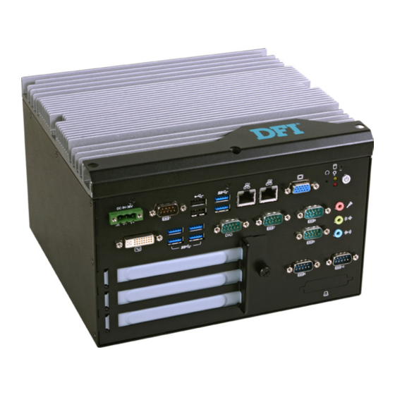
® Intel H81 Express Chipset (EC531/EC532-HD) ® Intel C226 Express Chipset (EC532-DL) 2 LAN ports 6 COM ports Display 1 VGA, 1 DVI-I 2 Type A USB 2.0 ports, 6 Type A USB 3.0 ports Power 9~36V DC-in Front View Chapter 1 Introduction www.dfi.com... -
Page 7: Specifications
Chapter 1 Specifications Expansion • EC531-HD - 2 PCI slots - 1 PCIe x16 slot Processor System • EC531/EC532-HD - 1 Mini PCIe slot ® - 4th Generation Intel Core processors (22nm process technology) : Supports USB and PCIe signals ® : Intel Core i7-4770TE (8M Cache, up to 3.3 GHz);... - Page 8 HDD LED Indicates the status of the hard drive. Status LED Indicates the status as below. Status LED Suspend Mode S4, S5 Quick Blink Slow Blink Always ON LED Action (cycle 1 sec) (cycle >1 sec) Chapter 1 Introduction www.dfi.com...
-
Page 9: Mechanical Dimensions
Chapter 1 Mechanical Dimensions Chassis Dimensions 222.00 153.80 Left View Front View Right View Chapter 1 Introduction www.dfi.com... - Page 10 Chapter 1 Motherboard Dimensions 0.00 21.00 34.00 50.00 55.00 63.70 77.67 81.00 98.57 98.57 106.44 110.73 120.19 151.65 152.73 152.73 160.85 174.83 198.81 210.00 206.89 215.00 Chapter 1 Introduction www.dfi.com...
-
Page 11: Chapter 2 - Getting Started
Please refer to your operating system manual for instructions on installing an operating system. Installing the Drivers The system requires you to install drivers for some devices to operate properly. Refer to the Supported Software chapter for instructions on installing the drivers. Chapter 2 Getting Started www.dfi.com... -
Page 12: Chapter 3 - Installing The Devices
Chapter 3 Chapter 3 - Installing the Devices 5. The SODIMM sockets, Mini PCIe slot and SATA drive bay are readily accessible after remov- ing the chassis cover. Removing the Chassis Cover 1. Make sure the system and all other peripheral devices connected to it have been powered-off. 2. -
Page 13: Installing The Sodimm
Chapter 3 Installing the SODIMM 3. Grasping the module by its edges, align the module into the socket at an approximately 30 degrees angle. Apply firm even pressure to each end of the module until it slips down into the socket. The contact fingers on the edge of the module will almost completely disappear 1. -
Page 14: Installing The 2.5" Sata Drive
Chapter 3 Installing the 2.5” SATA Drive 3. Connect the SATA power/data connector on the SATA drive to the SATA power/data cable secured on the HDD bracket. Then, align mounting holes of the SATA drive with mounting holes on the HDD bracket and use the provided mounting screws to secure the drive in place. - Page 15 Chapter 3 SATA power/data SATA power connector connector Mounting screw SATA data connector 5. Connect the SATA power cable and SATA data cable to the SATA power connector and the SATA data connector respectively on the system board. SATA power connector SATA data connector Chapter 3 Installing the Devices www.dfi...
-
Page 16: Installing The Mini Pcie And/Or Msata Card
Chapter 3 Installing the Mini PCIe and/or mSATA Card 3. Grasping the Mini PCIe card by its edges, align the card into the slot at an approximately 30 degrees angle. Apply fi rm even pressure to each end of the card until it slips down into the slot. -
Page 17: Installing The Pci And Pcie Expansion Cards
When inserting expansion cards into the system unit, please select a standard card within 190mm (as the following pictures show) in order to fit expansion slots. Brackets PCIe x16 EC531-HD Brackets PCIe x16 PCIe x16 Mechanical Drawing for Expansion Cards... - Page 18 3. Insert one expansion card with a bracket into PCIe slots and PCI slots respectively that are on the riser card and secure the bracket in place. PCIe x16 PCI card H320-2P1E for EC531-HD Rear View PCIe x16 PCIe x16 card...
-
Page 19: Installing The Cpu
Chapter 3 Installing the CPU 4. The system board is equipped with a surface mount LGA 1150 socket. This socket is exclu- sively designed for installing a LGA 1150 packaged Intel CPU. 1. Make sure the system and all other peripheral devices connected to it have been powered- off. - Page 20 Chapter 3 6. Lifting the load lever will at the same time lift the load plate and lift the load lever up to 8. Insert the CPU into the socket. The gold triangular mark on the CPU must align with the the angle as the photo shown below.
- Page 21 Chapter 3 10. Hook the load lever under the retention tab. Important: The CPU will fit in only one orientation and can easily be inserted without exerting any force. Load lever Retention tab 9. Close the load plate then push the load lever down. While closing the load plate, make sure the front edge of the load plate slides under the retention knob.
-
Page 22: Chapter 4 - Jumper Settings
Chapter 4 Chapter 4 - Jumper Settings USB Power Select Jumper Settings - System Board Clear CMOS Data 1-2 On: Normal (default) 1-2 On: +5V USB 1-2 (default) (JP1) 2-3 On: Clear CMOS Data 2-3 On: +5V_standby USB 8-9 (JP2) If you encounter the following, a) CMOS data becomes corrupted. -
Page 23: Auto Power-On Select
Chapter 4 Auto Power-on Select PS/2 Keyboard/Mouse Power Select 1-2 On: +5V 2-3 On: (default) +5V_standby 1-2 On: Power-on via power button (default) 2-3 On: Power-on via AC power JP7 is used to select the method of powering on the system. If you want the system to pow- er-on whenever AC power comes in, set JP7 pins 2 and 3 to On. -
Page 24: Com 1/Com 2 Rs232/422/485 Select
Chapter 4 COM 1/COM 2 RS232/422/485 Select COM 1 JP15 1 2 3 4 5 1 2 3 4 5 1 2 3 4 5 JP12 JP17 6 7 8 9 6 7 8 9 6 7 8 9 COM 2: RS422 RS232 RS485... -
Page 25: Com 1/Com 2 Rs232/Power Select
Chapter 4 COM 1/COM 2 RS232/Power Select Mini PCIe Signal Select COM 2: RS232/422/485 JP18 1-4-7-10, 2-5-8-11 On: PCIe (default) 1-3 (RI), 2-4 (DCD) On: RS232 (default) 2-5-8-11, 3-6-9-12 On: mSATA 3-5 (+5V), 4-6 (+12V) On: COM 1: RS232 with power RS232/422/485 JP14 JP9 is used to select the Mini PCIe signal: PCIe or mSATA. -
Page 26: Mini Pcie Power Select
Chapter 4 Mini PCIe Power Select Jumper Settings - I/O Board USB Power Select 1-2 On: +3.3V 2-3 On: +3.3V_standby (default) 1-2 On: +5V (default) 2-3 On: +5V_standby JP6 is used to select the power supplied with the Mini PCIe. JP4 and JP5 are used to select the power of the USB ports. -
Page 27: Com 7/Com 8 Rs232/422/485 Select
Chapter 4 COM 7/COM 8 RS232/422/485 Select COM 7/COM 8 1 2 3 4 5 1 2 3 4 5 1 2 3 4 5 COM 7/COM 8: RS232/422/485 COM 7 COM 8 6 7 8 9 6 7 8 9 6 7 8 9 RS422 RS232... -
Page 28: Com 7/Com 8 Rs232/Power Select
Chapter 4 COM 7/COM 8 RS232/Power Select Digital I/O Power Select COM 7/COM 8: RS232/422/485 COM 7 COM 8 JP10 2-3 On: +5V 1-2 On: +5V_standby (default) JP18 JP14 JP10 is used to select the power of DIO (Digital I/O) signal. 1-3 (RI), 2-4 (DCD) On: 3-5 (+5V), 4-6 (+12V) On: RS232 (default) -
Page 29: Digital I/O Output State
Chapter 4 Digital I/O Output State Digital I/O DIO 1-4 DIO 6-9 (JP9) (JP8) 1-2 On: +5V or 2-3 On: GND +5V_standby (default) Based on the power level of DIO (Digital I/O) selected on JP10, JP9 (DIO pin 1-4) and JP8 (DIO pin 6-9) are used to select the state of DIO output: pull high or pull low. -
Page 30: Chapter 5 - Ports And Connectors
Chapter 5 Chapter 5 - Ports and Connectors The front panel I/O ports consist of the followings: Front Panel I/O Ports EC531/EC532 - HD6881 • 1 DC-in power jack: 3-pole terminal block • 1 VGA port • 1 DVI-I port •... -
Page 31: Rj45 Lan Ports
Chapter 5 RJ45 LAN Ports EC532 - DL1040 • 1 DC-in power jack: 3-pole terminal block • 1 VGA port • 2 RJ45 LAN ports • 1 RS232 Serial COM port • 2 USB 3.0 (Type A) ports • 2 USB 2.0 (Type A) ports •... -
Page 32: Com (Serial) Ports
Chapter 5 COM (Serial) Ports COM 1, COM 7 and COM 8 COM 9 COM 6, COM 9 and COM 10: 1 2 3 4 5 1 2 3 4 5 1 2 3 4 5 RS232 COM 10 6 7 8 9 6 7 8 9 6 7 8 9 COM 8... -
Page 33: Vga Port
Chapter 5 USB Ports VGA Port USB 3.0 USB 3.0 USB 2.0 The USB device allows data exchange between your computer and a wide range of simultane- The VGA port is used for connecting a VGA monitor. Connect the monitor’s 15-pin D-shell cable ously accessible external Plug and Play peripherals. -
Page 34: Dc-In
Chapter 5 DC-in 8-bit GPIO GPIO DC-in The Digital I/O connector provides powering-on function to an external device that is con- nected to this connector. This jack provides maximum of 120W power and is considered a low power solution. Connect Digital Output/Input Pins Pin Assignment... -
Page 35: Audio Jacks
Chapter 5 Audio jacks DVI-I Port DVI-I The DVI-I port is used to connect an LCD monitor. Connect the display device’s cable con- nector to the DVI-D port. After plugging the cable connector into the port, gently tighten the cable screws to hold the connector in place. Rear Audio The system board is equipped with 3 audio jacks. -
Page 36: I/O Connectors
Chapter 5 I/O Connectors Parallel Connector Power Connector Parallel Ground +12V +12V Power +12V Ground Use a power supply that complies with the ATX12V Power Supply Design Guide Version 1.1. An ATX12V power supply unit has a standard 4-pin ATX main power connector that must be inserted into the 4-pin connector. -
Page 37: Cooling Fan Connectors
Chapter 5 Cooling Fan Connectors The fan connectors are used to connect cooling fans. The cooling fans will provide adequate airflow throughout the chassis to prevent overheating the CPU and system board components. BIOS Setting The Advanced menu (“PC Health Status” submenu) of the BIOS will display the current speed of the cooling fans. -
Page 38: Front Panel Connector
Chapter 5 Front Panel Connector SMBus Connector SMBUS Data Front PWR-LED Panel HDD-LED SMBus RESET-SW PWR-BTN +3.3V_standby SMBUS_Alert SMBUS Clock HDD-LED - HDD LED This LED will light when the hard drive is being accessed. RESET SW - Reset Switch The SMBus (System Management Bus) connector is used to connect SMBus devices. -
Page 39: Sata (Serial Ata) Connectors
Chapter 5 SATA (Serial ATA) Connectors SATA (Serial ATA) Power Connectors SATA 1 SATA Power 1 +12V Ground SATA 0 Ground SATA Power 0 SATA 3.0 6Gb/s Features These SATA power connectors supply power to the SATA drive. Connect one end of the pro- vided power cable to the SATA power connector and the other end to your storage device. -
Page 40: Ps/2 Keyboard/Mouse Connector
Chapter 5 PS/2 Keyboard/Mouse Connector Wake-On-PS/2 Keyboard/Mouse The Wake-On-PS/2 Keyboard/Mouse function allows you to use the PS/2 keyboard or PS/2 mouse to power-on the system. To use this function: PS/2 KB/MS • Jumper Setting JP3 must be set to “2-3 On: 5V_standby”. Refer to “PS/2 Keyboard/Mouse Power Select” in chapter 4 for more information. -
Page 41: Chassis Intrusion Connector
Chapter 5 Chassis Intrusion Connector Expansion Slots Mini PCI Express Chassis Intrusion Signal Ground PCI Express x16 PCI Express x4 The board supports the chassis intrusion detection function. Connect the chassis intrusion sensor cable from the chassis to this connector. When the system’s power is on and a chassis intrusion occurred, an alarm will sound. -
Page 42: Standby Power Led
Chapter 5 Standby Power LED EXC Slot The EXC interface is used to install an EXC card for I/O expansion. Standby Power LED This LED will lit red when the system is in the standby mode. It indicates that there is power on the system board. -
Page 43: Battery
Chapter 5 Battery Battery The lithium ion battery powers the real-time clock and CMOS memory. It is an auxiliary source of power when the main power is shut off. Safety Measures • Danger of explosion if battery incorrectly replaced. • Replace only with the same or equivalent type recommend by the manufacturer. -
Page 44: Chapter 6 - Mounting Options
Chapter 6 Chapter 6 - Mounting Options 2. Use the provided mounting screws to secure the wall mount brackets on each side of the system unit. Wall Mount The wall mount kit includes the following: • 2 Wall mount brackets Mounting screw •... -
Page 45: Chapter 7 - Bios Setup
Chapter 7 Chapter 7 - BIOS Setup Legends Overview Keys Function The BIOS is a program that takes care of the basic level of communication between the CPU and peripherals. It contains codes for various advanced features found in this system board. Moves the highlight left or right to select a menu. -
Page 46: Main
Chapter 7 AMI BIOS Setup Utility Advanced The Advanced menu allows you to configure your system for basic operation. Some entries are Main defaults required by the system board, while others, if enabled, will improve the performance of your system or let you set some features according to your preference. The Main menu is the first screen that you will see when you enter the BIOS Setup Utility. - Page 47 Chapter 7 ACPI Power Management Configuration Trusted Computing This section is used to configure the ACPI power management. This section configures settings relevant to Trusted Computing innovations. Aptio Setup Utility - Copyright (C) 2012 American Megatrends, Inc. Aptio Setup Utility - Copyright (C) 2012 American Megatrends, Inc. Advanced Advanced Confi...
- Page 48 Chapter 7 CPU Configuration SATA Configuration This section is used to configure the CPU. It will also display the detected CPU information. This section is used to configure the settings of Serial ATA devices. Aptio Setup Utility - Copyright (C) 2012 American Megatrends, Inc. Aptio Setup Utility - Copyright (C) 2012 American Megatrends, Inc.
- Page 49 Chapter 7 When IDE mode is selected in the SATA Mode Selection, it will display the following When RAID mode is selected in the SATA Mode Selection, it will display the following information: information: Aptio Setup Utility - Copyright (C) 2012 American Megatrends, Inc. Advanced Aptio Setup Utility - Copyright (C) 2012 American Megatrends, Inc.
- Page 50 Chapter 7 Software Feature Mask Confi guration PCH-FW Configuration This section is used to configure the parameters of Management Engine Technology. RAID OROM/RST driver will refer to the SWFM configuration in order to enable or dis- able the features of the storage device. Aptio Setup Utility - Copyright (C) 2012 American Megatrends, Inc.
- Page 51 Chapter 7 AMT Configuration USB Configuration This section configures the parameters of Active Management Technology. This section is used to configure USB. Aptio Setup Utility - Copyright (C) 2012 American Megatrends, Inc. Aptio Setup Utility - Copyright (C) 2012 American Megatrends, Inc. Advanced Advanced Enables Legacy USB...
- Page 52 Chapter 7 Super IO Configuration Serial Port 0 Configuration and Serial Port 5 Configuration This section is used to configure the I/O functions supported by the onboard Super I/O chip. Sets parameters of serial port 0 (COM A) and serial port 5 (COM F). Aptio Setup Utility - Copyright (C) 2012 American Megatrends, Inc.
- Page 53 Chapter 7 Aptio Setup Utility - Copyright (C) 2012 American Megatrends, Inc. Aptio Setup Utility - Copyright (C) 2012 American Megatrends, Inc. Advanced Advanced Serial Port 2 Confi guration Serial Port 4 Confi guration Enable or Disable Serial Enable or Disable Serial Port (COM) Port (COM) Serial Port...
- Page 54 Chapter 7 Serial Port PC Health Status Enables or disables the serial port (COM). This section displays the hardware health monitor. Change Settings Aptio Setup Utility - Copyright (C) 2012 American Megatrends, Inc. Advanced Selects the IO/IRQ settings for the super I/O device. PC Health Status Smart Fan Function Setting...
- Page 55 Chapter 7 CPU Smart Fan Control Second Super IO Configuration When this feature is set to Automatic, the CPU’s fan speed will rotate according to the This section is used to configure the parameters of the system second super I/O chip. CPU’s temperature.
- Page 56 Chapter 7 Serial Port Network Stack Enables or disables the serial port (COM). This section is used to enable or disable UEFI network stack. Change Settings Aptio Setup Utility - Copyright (C) 2012 American Megatrends, Inc. Advanced Selects the IO/IRQ settings for the super I/O device. Network Stack [Disabled] Enable/Disable UEFI...
-
Page 57: Chipset
Chapter 7 Chipset Ipv4 PXE Support When enabled, Ipv4 PXE boot supports. When disabled, Ipv4 PXE boot option will not This section configures relevant chipset functions. be created. Ipv6 PXE Support Aptio Setup Utility - Copyright (C) 2012 American Megatrends, Inc. Main Advanced Chipset... - Page 58 Chapter 7 System Agent (SA) Configuration Graphics Configuration This section is used to configure the parameters of System Agent. This field configures the graphics settings. Aptio Setup Utility - Copyright (C) 2012 American Megatrends, Inc. Aptio Setup Utility - Copyright (C) 2012 American Megatrends, Inc. Chipset Chipset Graphics Confi...
- Page 59 Chapter 7 DVMT Pre-Allocated LCD Control Selects DVMT 5.0 Pre-Allocated (Fixed) Graphics Memory size used by the Internal This field configures the LCD control. Graphics Device. Please refer to the information below. Aptio Setup Utility - Copyright (C) 2012 American Megatrends, Inc. Aptio Setup Utility - Copyright (C) 2012 American Megatrends, Inc.
- Page 60 Chapter 7 NB PCIe Configuration Memory Configuration This field is used to configure the settings of NB PCI Express. This field only displays the memory configuration. Aptio Setup Utility - Copyright (C) 2012 American Megatrends, Inc. Aptio Setup Utility - Copyright (C) 2012 American Megatrends, Inc. Chipset Chipset NB PCIe Confi...
- Page 61 Chapter 7 PCH-IO Configuration PCI Express Configuration This section illustrates the PCH parameters. This field is used to configure the PCI Express settings. Aptio Setup Utility - Copyright (C) 2012 American Megatrends, Inc. Aptio Setup Utility - Copyright (C) 2012 American Megatrends, Inc. Chipset Chipset PCI Express Confi...
- Page 62 Chapter 7 Aptio Setup Utility - Copyright (C) 2012 American Megatrends, Inc. Aptio Setup Utility - Copyright (C) 2012 American Megatrends, Inc. Chipset Chipset PCI Express Root Port 5 [Enabled] Control the PCI Express PCI Express Root Port 7 [Enabled] Control the PCI Express PCIe Speed [Auto]...
- Page 63 Chapter 7 XHCI Mode USB Configuration Selects the operation mode of XHCI controller. These options are Auto, Enabled, This field is used to configure the USB settings. and Disabled. When Disabled is selected in the XHCI Mode, it will display the following information: Aptio Setup Utility - Copyright (C) 2012 American Megatrends, Inc.
- Page 64 Chapter 7 USB Ports Per-Port Disable Control PCH Azalia Configuration This field is used to control each of the USB ports (0~13) disabling. When enabled, This field is used to configure the PCH Azalia settings. it will display the following information: Aptio Setup Utility - Copyright (C) 2012 American Megatrends, Inc.
-
Page 65: Boot
Chapter 7 Boot CSM Parameters Aptio Setup Utility - Copyright (C) 2012 American Megatrends, Inc. Aptio Setup Utility - Copyright (C) 2012 American Megatrends, Inc. Boot Main Advanced Chipset Boot Security Save & Exit Even Logs Boot Confi guration This option controls if Number of seconds to Launch CSM [Enabled]... -
Page 66: Security
Chapter 7 Security Save & Exit Aptio Setup Utility - Copyright (C) 2012 American Megatrends, Inc. Aptio Setup Utility - Copyright (C) 2012 American Megatrends, Inc. Main Advanced Chipset Boot Security Save & Exit Even Logs Main Advanced Even Logs Chipset Boot Security... -
Page 67: Event & Logs
Chapter 7 Event & Logs Change Smbios Event Log Settings Press the <Enter> button to change the Smbios Event Log configuration. Aptio Setup Utility - Copyright (C) 2012 American Megatrends, Inc. Main Advanced Chipset Boot Security Save & Exit Event & Logs ... -
Page 68: Updating The Bios
Chapter 7 Updating the BIOS View Smbios Event Log Press the <Enter> button to change the Smbios Event Log configuration. To update the BIOS, you will need the new BIOS file and a flash utility, AFUDOS. EXE. Please contact technical support or your sales representative for the files. To execute the utility, type: Aptio Setup Utility - Copyright (C) 2012 American Megatrends, Inc. -
Page 69: Notice: Bios Spi Rom
Chapter 7 Notice: BIOS SPI ROM 1. The Intel Management Engine has already been integrated into this system board. Due to ® the safety concerns, the BIOS (SPI ROM) chip cannot be removed from this system board and used on another system board of the same model. 2. -
Page 70: Chapter 8 - Supported Software
“Setup”. If your product package does not include a CD/DVD, you can download the latest drivers from the DFI Download Center: http://www.dfi.com/DownloadCenter Once you are in the Download Center page, select your product or type the model name and click "Search"... - Page 71 Chapter 8 Auto Run Page (For Windows 7) Chapter 8 Supported Software www.dfi .com...
- Page 72 Chapter 8 Auto Run Pages (For Windows XP) Microsoft .NET Framework 3.5 (For Windows XP) Note: Before installing Microsoft .NET Framework 3.5, make sure you have updated your Windows XP operating system to Service Pack 3. To install the driver, click “Microsoft .NET Framework 3.5” on the main menu. 1.
- Page 73 Chapter 8 Intel Chipset Software Installation Utility 3. Click Exit. The Intel Chipset Software Installation Utility is used for updating Windows INF files so that ® the Intel chipset can be recognized and configured properly in the system. To install the utility, click “Intel Chipset Software Installation Utility” on the main menu. 1.
- Page 74 Chapter 8 Microsoft DirectX 9.0C (For Windows XP) 3. Go through the readme document for more installa- tion tips then click Next. To install the utility, click “Microsoft DirectX 9.0C Driver” on the main menu. 1. Click “I accept the agreement”...
- Page 75 Chapter 8 Intel HD Graphics Drivers (For Windows XP) 4. Setup is now installing the driver. Click Next to continue. To install the driver, click “Intel HD Graphics Drivers” on the main menu. 1. To start installation, click Next. 5. Click “Yes, I want to restart this computer now”...
- Page 76 Chapter 8 Intel HD Graphics Drivers (For Windows 7 and Windows 8) 3. Go through the readme document for system re- quirements and installation To install the driver, click “Intel HD Graphics Drivers” on the main menu. tips then click Next. 1.
- Page 77 Chapter 8 Intel Management Engine Drivers 3. Setup is currently installing the driver. After installation (For Windows 7and Windows 8) has completed, click Next. To install the driver, click “Intel Management Engine Drivers” on the main menu. 1. Setup is ready to install the driver.
- Page 78 Chapter 8 Audio Drivers Intel LAN Drivers (For Windows XP) To install the driver, click “Audio Drivers” on the main menu. The LAN drivers for Windows XP supporting on the Haswell system board has to be installed manually. When you want to install the LAN driver for Windows XP, please follow the steps below to accomplish the installation.
- Page 79 Chapter 8 6. Insert the installation disk 9. Click "Finish" to close the wizard. and make sure the selected drive is correct. (For 32-bit, the fi le name is “e1d5132.inf”.) 7. Select the device driver 10. After completing the instal- you want to install for this lation, the Network adapters hardware and then click...
- Page 80 Chapter 8 Intel LAN Drivers (For Windows 7 and Windows 8) 4. Click Install to begin the installation. To install the driver, click “Intel LAN Drivers” on the main menu. 1. Setup is ready to install the driver. Click Next. 5.
- Page 81 HW Utility 3. Click “Install” to begin the installation. DFI Utility provides information about the board, Watchdog,and DIO. To access the utility, click “HW Utility” on the main menu. Note: If you are using Windows 7, you need to access the operating system as an administrator to be able to install the utility.
- Page 82 Chapter 8 The DFI Utility icon will appear on the desktop. Double-click the icon to open the utility. HW Health Set Information WatchDog HW Health Chapter 8 Supported Software www.dfi .com...
- Page 83 Chapter 8 Intel USB 3.0 Drivers (For Windows 7) To install the driver, click “Intel USB 3.0 Driver” on the main menu. 1. Setup is ready to install the driver. Click Next. 2. Read the license agreement then click Yes. Chapter 8 Supported Software www.dfi...
- Page 84 Chapter 8 Intel USB 3.0 Host Drivers (For Windows 7 and Windows 8) 3. Go through the readme docu- ment for more installation tips then click Next. To install the driver, click “Intel USB 3.0 Host Drivers” on the main menu. 1.
- Page 85 Chapter 8 Intel Rapid Storage Technology 3. Click “finish“ to complete the installation. (For Windows 7 and Windows 8) The Intel Rapid Storage Technology is a utility that allows you to monitor the current status of the SATA drives. It enables enhanced performance and power management for the storage subsystem.
- Page 86 Chapter 8 3. Read the license agreement then 6. Click “Yes, I want to restart my click Yes. computer now” then click Finish. Restarting the system will allow the new software installation to take effect. 4. Go through the readme document for system requirements and instal- lation tips then click Next.
- Page 87 Chapter 8 Infineon TPM Driver and Tool (optional) 4. Enter the necessary information and then click Next. To install the driver, click “Infineon TPM driver and tool (option)” on the main menu. 1. The setup program is preparing to install the driver. 5.
- Page 88 Chapter 8 7. TPM requires installing the Micro- 10. Click “Yes“ to restart your system. soft Visual C++ package prior to installing the utility. Click Install. 8. The setup program is currently installing the Microsoft Visual C++ package. 9. Click Finish. Chapter 8 Supported Software www.dfi...
- Page 89 Chapter 8 Nuvton-SIO 4. Installing status. To install the driver, click “Nuvton-SIO” on the main menu. 1. The setup program is preparing to install the driver. 5. Click “Finish“ to exit the wizard after the installation is completed. 2. The setup program is now ready to install the utility.
- Page 90 Chapter 8 Adobe Acrobat Reader 9.3 To install the reader, click “Adobe Acrobat Reader 9.3” on the main menu. 1. Click Next to install or click Change Destination Folder to select another folder. 2. Click Install to begin installa- tion. 3.
-
Page 91: Chapter 9 - Digital I/O Programming Guide
Chapter 9 Chapter 9 - Digital I/O Programming Guide The Configuration Register (register 3) configures the direction of the I/O pins. If a bit in this register is set to 1, the corresponding port pin is enabled as an input with a high-impedence Register Description output driver. - Page 92 Chapter 9 Function Description GPIO Output Process I2CWriteByte(SlaveAddr, SubAddr, Data): #defi ne SLAVE_ADDR 0x42 Write a Byte data to a specified I2C Device. #defi ne INPUT_PORT 0x00 #defi ne OUTPUT_PORT 0x01 I2CReadByte(SlaveAddr, SubAddr, *Data): 0x02 #defi ne INVERSION_PORT Read a Byte data from a specified I2C Device. 0x03 #defi...
-
Page 93: Appendix A - Watchdog Sample Code
Appendix A Appendix A - Watchdog Sample Code ;Software programming example: ;--------------------------------------------- ;(1) Enter Super IO Confi guration mode ;--------------------------------------------- DX,4EH AL,87H DX,AL DX,AL ;------------------------------------------------------------------------------------------- ;(2) Confi guration Logical Device 8, register CRF0/CRF1 (WDT Control/WDT timer) ;------------------------------------------------------------------------------------------- DX,4EH AL,07H ;Ready to Program Logical Device DX,AL DX,4FH AL,08H... -
Page 94: Appendix B - System Error Message
Appendix B Appendix B - System Error Message Hard Disk(s) fail (20) When the BIOS encounters an error that requires the user to correct something, either a beep HDD initialization error. code will sound or a message will be displayed in a box in the middle of the screen and the message, PRESS F1 TO CONTINUE, CTRL-ALT-ESC or DEL TO ENTER SETUP, will be shown in Hard Disk(s) fail (10) the information box at the bottom. -
Page 95: Appendix C - Troubleshooting
Appendix C Appendix C - Troubleshooting Checklist The picture seems to be constantly moving. Troubleshooting Checklist 1. The monitor has lost its vertical sync. Adjust the monitor’s vertical sync. 2. Move away any objects, such as another monitor or fan, that may be creating a magnetic This chapter of the manual is designed to help you with problems that you may encounter field around the display. - Page 96 Appendix C Hard Drive System Board 1. Make sure the add-in card is seated securely in the expansion slot. If the add-in card is Hard disk failure. loose, power off the system, re-install the card and power up the system. 1.
Need help?
Do you have a question about the EC531-HD and is the answer not in the manual?
Questions and answers