
Related Manuals for DFI EC500-ADS


Summary of Contents for DFI EC500-ADS
- Page 1 EC500-ADS Modular-Designed Embedded System User’s Manual © October 05, 2023 DFI Inc.
- Page 2 1. The changes or modifications not expressly approved by the party responsible for com- are the properties of the respective owners. pliance could void the user’s authority to operate the equipment. 2. Shielded interface cables must be used in order to comply with the emission limits. User's Manual | EC500-ADS...
-
Page 3: Table Of Contents
USB Power Control ......................28 Tls Auth Configuration ....................29 Chipset ..........................30 System Agent (SA) Configuration ................30 PCH-IO Configuration ....................31 PCH-IO Configuration► PCI Express Configuration ..........31 ► SATA Configuration .............32 PCH-IO Configuration PCH-IO Configuration ► HD Audio Configuration ..........32 User's Manual | EC500-ADS... - Page 4 The manual is subject to change and update without notice, and may be based on editions that do not resemble your actual products. Please visit our website or contact our sales representa- • 1 EC500-ADS system unit tives for the latest editions. •...
- Page 5 Make sure the system is placed or mounted correctly and stably to prevent the chance of dropping or falling may cause damage. • The openings on the system shall not be blocked and shall be kept in distance from User's Manual | EC500-ADS...
-
Page 6: Chapter 1 - Introduction
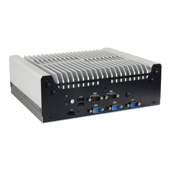
HDMI/DP port. The HDMI COM1 COM3 HDMI male connector shall align to the left of the port as illustrated here. The insertion is fairly effortless and please reframe from forcing the insertion to prevent damage. User's Manual | EC500-ADS... -
Page 7: Dimensions
3x M.2 slots (1x M.2 2230 E key, 1x M.2 3042/3052 B key, 1x M.2 2280 M key) Rich I/O 2 GbE, 6 COM, 4 USB 3.1, 2 USB 2.0 Support 5G Communication Support 5G communication User's Manual | EC500-ADS... -
Page 8: Specifications
1 x M.2 2230 E key (PCIe/USB 2.0) 1 x M.2 3042/3052 B key (PCIe) AUDIO Audio Codec Realtek ALC888 ETHERNET Controller 2 x Intel I225IT PCIe (10/100/1000Mbps) ® Indicators 1 x Status LED 1 x HDD LED User's Manual | EC500-ADS... - Page 9 -20 to 70°C (SSD or M.2 storage) Storage Temperature -20 to 85°C Relative Humidity 5 to 95% RH (non-condensing) STANDARDS AND Shock Half sine wave 3G, 11ms, 3 shock per axis CERTIFICATIONS Vibration IEC68-2-64 Certification CE, FCC Class A User's Manual | EC500-ADS...
-
Page 10: Chapter 2 - Hardware Installations
The 12 screws on each side of the system are used to secure the cover to the chassis. Remove the screws and put them in a safe place for later use. Front View Left View Rear View Right View User's Manual | EC500-ADS... -
Page 11: Installing An Antenna
Connect the internal cable to the board's antenna connector, screw the antenna connector through the antenna hole with washers and nuts, and screw on the antenna as illustrated below. Antenna Chassis Wall Module Connector Cable Antenna Connector Washer User's Manual | EC500-ADS... -
Page 12: Expansion Slots
The heat sink M.2 Module: M.2 M Key Remove four screws and put them in a safe place for later use. After removing the screws, gently pull the SSD slot out of the system. M.2 M Key User's Manual | EC500-ADS... -
Page 13: Installing The M.2 Module
Screw tight the card onto the stand-off with a screw driver and a stand-off screw until the gap between the card and the stand-off closes up. The card should be lying parallel to the board when it’s correctly mounted. User's Manual | EC500-ADS... -
Page 14: Installing Micro Sim Card
X Installing Micro SIM Card Step 2: Step 1: Lift the cover. Slide the cover to unlock. Step 3: Step 4: Orient the SIM card and place it into the socket. Close the cover and slide the cover to lock. User's Manual | EC500-ADS... -
Page 15: Mounting Options
Locate the mount- ing holes on the bottom of the system as shown in the photo. Screw on the two brackets onto the system with six screws as illustrated below. Wall Mount Bracket Wall Mount Bracket User's Manual | EC500-ADS... -
Page 16: Chapter 3 - Bios Settings
When “X” appears on the left of a particular field, it indicates that a submenu which contains additional options are available for that field. To display the submenu, move the highlight to that field and press <Enter>. User's Manual | EC500-ADS... -
Page 17: Main
The time format is <hour>, <minute>, <second>. The time is based on the 24-hour military-time clock. For example, 1 p.m. is 13:00:00. Hour displays hours from 00 to 23. Minute displays min- utes from 00 to 59. Second displays seconds from 00 to 59. User's Manual | EC500-ADS... -
Page 18: Cpu Configuration
Enables this field for Windows XP and Linux which are optimized for Hyper-Threading technol- ogy. Select disabled for other OSes not optimized for Hyper-Threading technology. When dis- abled, only one thread per enabled core is enabled. Enable / Disable AES (Advanced Encryption Standard) User's Manual | EC500-ADS... -
Page 19: Power & Performance ► Cpu-Power Management Control
Enable or disable turbo mode of the processor. This field will only be displayed when EIST is Check to enable render standby support. enabled. Configure Turbo Options Configure Turbo Options C states Enable or disable CPU Power Management. It allows CPU to enter "C states" when it’s idle and nothing is executing. User's Manual | EC500-ADS... -
Page 20: Pch-Fw Configuration
MEBx Setup. This option does not disable manageability features in FW. ME Unconfig on RTC Clear When disabled, ME will not be unconfigured on RTC Clear. Firmware Update Configuration Configure Management Engine Technology Parameters. Note: The sub-menus are detailed in following sections. User's Manual | EC500-ADS... -
Page 21: Nct6126D Super Io Configuration
NCT6126D Super IO Configuration NCT6126D Super IO Configuration ► Serial Port 1,2 Configuration Serial Port Enable or disable serial port. Electrical Interface Mode Choose mode between RS232 / RS485 / RS422 Note: The sub-menus are detailed in following sections. User's Manual | EC500-ADS... -
Page 22: Nct6126D Super Io Configuration ► Serial Port 3,4 Configuration
Serial Port Serial Port Enable or disable serial port. Enable or disable serial port. Electrical Interface Mode Electrical Interface Mode Choose mode between RS232 / RS485 / RS422 Choose mode between RS232 / RS485 / RS422 User's Manual | EC500-ADS... -
Page 23: Nct6126D Hw Monitor
Fan Speed Count 1 field. • Fan Speed Count 1 to Fan Speed Count 4 Set the fan speed, the value ranging from 1-100%, 100% being full speed. The fans will operate according to the specified boundary temperatures above-mentioned. User's Manual | EC500-ADS... -
Page 24: Serial Port Console Redirection
Select data bits: 7 bits or 8 bits. Parity Select parity bits: None, Even, Odd, Mark or Space. Stop Bits Select stop bits: 1 bit or 2 bits. Flow Control Select flow control type: None or RTS/CTS. User's Manual | EC500-ADS... -
Page 25: Serial Port Console Redirection ► Console Redirection Settings
Enable VT-UTF8 Combination Key Support for ANSI/VT100 terminals. Recorder Mode With this mode enbaled only text will be sent. This is to capture Terminal data. Resolution 100x31 Enables or disables extended terminal resolution Putty KeyPad Select FunctionKey and KeyPad on Putty. User's Manual | EC500-ADS... -
Page 26: Acpi Configuration
• S0 State The system automatically powers on after power failure. taken from Hub descriptor. • S5 State The system enter soft-off state after power failure. Power-on signal input is required to power up the system. User's Manual | EC500-ADS... -
Page 27: Network Stack Configuration
Set the wait time in seconds to press ESC key to abort the PXE boot. Use either +/- or nu- meric keys to set the value. Media detect count Set the number of times the presence of media will be checked. Use either +/- or numeric keys to set the value. User's Manual | EC500-ADS... -
Page 28: Dfi Wdt Configuration
Advanced Advanced USB Power Control DFI WDT Configuration USB Power 5V_Dual: Support system wake from S3/S4 by USB KB&MS Watchdog Timer 5V: No Support system wake from S3/S4 by USB KB&MS Enable or disable Watchdog Timer. User's Manual | EC500-ADS... -
Page 29: Tls Auth Configuration
Chapter 3 BIOS SETTINGS Advanced Tls Auth Configuration Server CA Configuration Press <Enter> to configure Server CA. User's Manual | EC500-ADS... -
Page 30: Chipset
Chapter 3 BIOS SETTINGS X Chipset Chipset System Agent (SA) Configuration Graphics Configuration Graphics Configuration VMD setup menu VMD Configuration Settings PCI Express Configuration : VT-d VT-d capability. User's Manual | EC500-ADS... -
Page 31: Pch-Io Configuration
Select one of the PCI Express channels and press enter to configure the following settings. PCI Express Configuration Settings LAN1, LAN2, M.2-M, M.2-E, M.2-B SATA Configuration Control the PCI Express Root Port. SATA Device Otpions Settings HD Audio Configuration HD Audio Subsystem Configuration Settings User's Manual | EC500-ADS... -
Page 32: Pch-Io Configuration ► Sata Configuration
This field is used to select SATA speed generation limit: Auto, Gen1, Gen2 or Gen3. Enabled HDA will be unconditionally enabled. Ports and Hot Plug Enable or disable the Serial ATA port and its hot plug function. User's Manual | EC500-ADS... -
Page 33: Security
Clear the database from the NVRAM, including all the keys and signatures installed in the Key Management menu. Press Enter and a prompt will show up for you to confirm. Key Management Enables expert users to modify Secure Boot Policy variables without full authentication. User's Manual | EC500-ADS... -
Page 34: Boot
Select this option to save BIOS configuration settings to a USB flash device. ► Restore Setting from file This field will appear only when a USB flash device is detected. Select this field to restore set- ting from the USB flash device. User's Manual | EC500-ADS... -
Page 35: Mebx
MAC address should be burned or not. c. After updating unique MAC Address from manufacturing, NVM will be protected immediately after power cycle. Users cannot update NVM or MAC address. User's Manual | EC500-ADS...
Need help?
Do you have a question about the EC500-ADS and is the answer not in the manual?
Questions and answers