DFI EC800-AL User Manual
Fanless embedded system
Hide thumbs
Also See for EC800-AL:
- Installation manual (7 pages) ,
- Quick installation manual (10 pages)
Table of Contents
Advertisement
Quick Links
Download this manual
See also:
Installation Manual
Advertisement
Table of Contents

Related Manuals for DFI EC800-AL


Summary of Contents for DFI EC800-AL
- Page 1 EC800-AL Fanless Embedded System User’s Manual A46810817 Chapter 1 Introduction...
- Page 2 Copyright FCC and DOC Statement on Class B This publication contains information that is protected by copyright. No part of it may be re- This equipment has been tested and found to comply with the limits for a Class B digital produced in any form or by any means or used to make any transformation/adaptation without device, pursuant to Part 15 of the FCC rules.
-
Page 3: Table Of Contents
Chapter 7 - BIOS Setup ......28 Key Features ................6 Specifications ................7 Chapter 8 - Supported Software ....40 Getting to Know the EC800-AL ..........8 Mechanical Dimensions ............9 Chapter 2 - Getting Started ...... 10 Chapter 3 - Installing Devices ....11 Removing the Chassis Cover ........... -
Page 4: About This Manual
About this Manual Static Electricity Precautions An electronic file of this manual can be obtained from the DFI website at www.dfi.com. To It is quite easy to inadvertently damage your PC, system board, components or devices even download the user’s manual from our website, please go to Support > Download Center. On before installing them in your system unit. -
Page 5: Safety Precautions
• Unplug the power cord before removing the system chassis cover for installation or servic- ing. After installation or servicing, cover the system chassis before plugging the power cord. • One EC800-AL system unit • One CD disk includes • Danger of explosion if battery incorrectly replaced. -
Page 6: Chapter 1 - Introduction
Chapter 1 Chapter 1 - Introduction Overview Key Features Model Name EC800-AL Processor Intel Atom ® Processor E3900 Series Audio One line-out and microphone port Two LAN ports Two serial ports One DVI (or VGA) Display Two Mini DisplayPort (or Micro HDMI) Two USB 3.0 and two USB 2.0 Type A ports... -
Page 7: Specifications
Chapter 1 Specifications Processor Intel Atom ® Processor E3900 Series, BGA 1296 I/O Ports and • Front Panel Intel Atom ® x7-E3950 Processor, Quad Core, 2M Cache, 1.6GHz (2.0GHz), 12W LED Indicators - 2 RJ-45 LAN ports ® Intel Atom x5-E3940 Processor, Quad Core, 2M Cache, 1.6GHz (1.8GHz), 9W - 1 RS-232/422/485 serial port with DB-9 connector ®... -
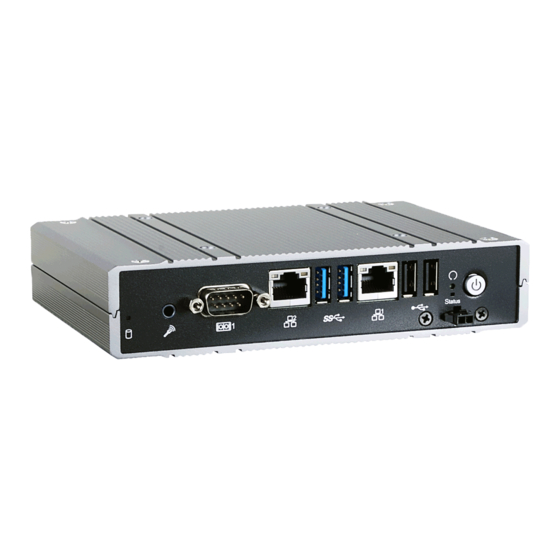
Page 8: Getting To Know The Ec800-Al
Chapter 1 Getting to Know the EC800-AL Front View Rear View Reset Button LAN 1 LAN 2 Antenna hole Antenna hole Power Button (green) DC-in Mic-in Status LED (blue) HDD LED COM 1 USB 3.0 USB 2.0 Mini DisplayPort (blue) -
Page 9: Mechanical Dimensions
Chapter 1 Mechanical Dimensions Chassis Dimension Rear View Top View 35.10 Left View Right View 161.00 Front View Chapter 1 Introduction... -
Page 10: Chapter 2 - Getting Started
Chapter 2 Chapter 2 - Getting Started Preparing the System Before you start using the system, you need the following items: • AC power adapter or other means of power supply • DVD-ROM drive (for installing software/drivers) • Screwdriver Installing Devices The following devices can be installed in the system. -
Page 11: Chapter 3 - Installing Devices
Chapter 3 Chapter 3 - Installing Devices Removing the Chassis Cover Lift the cover to open the system. The M.2 and Mini PCIe sockets are readily accessible after Please observe the following guidelines and follow the procedure to open the system. removing the bottom cover. - Page 12 Chapter 3 Installing an M.2 Card To install a 30mm M.2 card: Align the notch at the edge of the M.2 card with the key in the connector. The system is equipped with two M.2 sockets, supporting one M.2 22x42mm (B key) and one Insert the M.2 card into the connector.
- Page 13 Chapter 3 Installing a Mini PCIe or an mSATA Card To install both 42mm and 30mm M.2 cards: Align the notch at the edge of the 30mm M.2 card with the key in the connector. The system board is equipped with 1 Mini PCIe slot. Insert the 30mm M.2 card into the connector.
-
Page 14: Chapter 4 - Jumper Settings
Chapter 4 Chapter 4 - Jumper Settings Auto Power-on Select (bottom side) Clear CMOS Data (bottom side) Clear CMOS Clear CMOS SPI ROM Battery SPI ROM Battery JP1 JP7 JP1 JP7 PCIe/SATA PCIe/SATA 1-2 On: Auto power-on Auto power-on Normal (default) 1-2 On: Power-on via power button (default) - Page 15 Chapter 4 Mini PCIe (CN15) Mini PCIe/mSATA Select (bottom side) M.2 (CN12) PCIe/SATA Select (bottom side) Clear CMOS Clear CMOS SPI ROM Battery SPI ROM Battery JP1 JP7 JP1 JP7 PCIe/SATA PCIe/SATA Auto power-on Auto power-on 1-2 On: SATA (default) 2-3 On: PCIe Mini-PCIe/mSATA JP2, JP3...
- Page 16 Chapter 4 COM 2/DIO Select (top side) COM 1 LAN 2 Power LAN 1 HDD LED USB 2.0 MIC-in Realtek Intel WGI211AT ALC262 USB 3.0 Buzzer SMBus (J19) Power on/off (J11) Intel WGI211AT Standby LED DDR4 Intel Atom ® DDR4 DDR4 E3900 Series DDR4...
-
Page 17: Chapter 5 - Ports And Connectors
Chapter 5 Chapter 5 - Ports and Connectors Rear Panel I/O Ports Front Panel I/O Ports Antenna hole Antenna hole Reset Button DC-in HDD LED Power Button Mic-in Status LED LAN 2 LAN 1 (blue) COM 1 DVI-D Mini DisplayPort USB 3.0 USB 2.0 COM 2... -
Page 18: Usb Ports
Chapter 5 USB Ports Audio Ports USB 2.0 USB 3.0 Mic-in COM 1 COM 1 Power LAN 2 LAN 2 LAN 1 HDD LED Power LAN 1 HDD LED USB 2.0 MIC-in USB 2.0 MIC-in Intel Realtek Intel Realtek WGI211AT ALC262 WGI211AT ALC262... -
Page 19: Com Ports/ 8-Bit Dio
Chapter 5 COM Ports/ 8-bit DIO COM 1 / COM 2 1 2 3 4 5 1 2 3 4 5 1 2 3 4 5 COM 1: RS232/RS422/RS485 6 8 9 6 8 9 COM 1 LAN 2 Power LAN 1 HDD LED USB 2.0... -
Page 20: Rj45 Lan Ports
Chapter 5 RJ45 LAN Ports DC-in LAN 2 LAN 1 COM 1 LAN 2 Power LAN 1 HDD LED USB 2.0 MIC-in Intel Realtek COM 1 WGI211AT ALC262 USB 3.0 Power LAN 2 LAN 1 HDD LED Buzzer SMBus (J19) USB 2.0 MIC-in Intel... -
Page 21: Display Outputs
Chapter 5 Display Outputs COM 1 LAN 2 Power LAN 1 HDD LED USB 2.0 MIC-in Intel Realtek WGI211AT ALC262 USB 3.0 Buzzer SMBus (J19) Power on/off (J11) Intel WGI211AT Standby LED DDR4 Intel Atom ® DDR4 DDR4 E3900 Series DDR4 JP8, JP9 COM 2/DIO... -
Page 22: I/O Connectors
Chapter 5 I/O Connectors SMBus Connector (top side) Expansion Connectors (bottom side) COM 1 LAN 2 Power LAN 1 HDD LED M.2 Type 2242 (PCIe 2.0 x2/USB/SATA) USB 2.0 MIC-in Intel Realtek M.2 Type 2230 (PCIe/USB) WGI211AT ALC262 Mini PCIe (PCIe/USB/SATA) USB 3.0 Buzzer SMBus (J19) -
Page 23: Leds (Top Side)
Chapter 5 LEDs (top side) Battery (bottom side) HDD LED Battery COM 1 LAN 2 Power LAN 1 HDD LED USB 2.0 MIC-in Realtek Intel Battery (J7) WGI211AT ALC262 USB 3.0 Buzzer SMBus (J19) Power on/off (J11) Intel WGI211AT Clear CMOS Standby LED DDR4 SPI ROM... -
Page 24: Power Switch (Top Side)
Chapter 5 Power Switch (top side) USB 2.0 (top side) COM 1 LAN 2 Power LAN 1 HDD LED COM 1 USB 2.0 MIC-in Intel Realtek LAN 2 Power LAN 1 HDD LED WGI211AT ALC262 USB 3.0 USB 2.0 MIC-in Intel Realtek Buzzer... -
Page 25: Chapter 6 - Mounting Options
Chapter 6 Chapter 6 - Mounting Options Align the mounting holes of the wall mount bracket with the screw holes of the system and use the provided mounting screws to secure the wall mount brackets on both sides of Wall Mount the system. -
Page 26: Vesa Mount
Chapter 6 VESA Mount Attach the VESA bracket A to the back of your display using four screws as shown in the picture below. The vesa mount kit includes the following: • 1 VESA mount bracket A • 2 VESA mount bracket B •... -
Page 27: Din Rail Mount
Chapter 6 DIN-rail Mount 2. Align the mounting holes on the system and the mounting holes on the bracket, and then use the screws removed in step 1 to secure the bracket in place. The DIN Rail mount kit includes the following: 3. -
Page 28: Chapter 7 - Bios Setup
Chapter 7 Chapter 7 - BIOS Setup Legends Overview Keys Function The BIOS is a program that takes care of the basic level of communication between the CPU Right and Left and peripherals. It contains codes for various advanced features found in this system board. Moves the highlight left or right to select a menu. - Page 29 Chapter 7 Insyde BIOS Setup Utility Advanced The Advanced menu allows you to configure your system for basic operation. Some entries are Main defaults required by the system board, while others, if enabled, will improve the performance of your system or let you set some features according to your preference. The Main menu is the first screen that you will see when you enter the BIOS Setup Utility.
- Page 30 Chapter 7 CPU Configuration ACPI Configuration This section configures the CPU. This section configures system ACPI parameters. EIST Enable or disable the ERP (Energy-related Products) support. Disable the ERP support to Enable or disable the Enhanced Intel SpeedStep Technology, which helps optimize ®...
- Page 31 Chapter 7 Audio Configuration Video Configuration This section configures the audio settings. This section configures the video settings. Audio Controller Primary Display Control the detection of the high-definition audio devices. Select the primary display for the system from the following options: IGD: integrated graphics devices Disabled PCIe: PCIe graphics devices...
- Page 32 Chapter 7 SATA Configuration This section configures SATA devices. It also shows the information about the installed SATA drives. SATA Speed Selection SATA Controller Select Serial ATA device speed from these options: Gen1 (1.5 Gbit/s), Gen2 (3 Gbit/s) or Enable or disable the Serial ATA controller. Gen 3 (6 Gbit/s).
- Page 33 Chapter 7 PCI Express Configuration This section configures the settings of PCI Express root ports. PCI Express Root Port 1 Controls the PCIe signal of the M.2 Type 2242 B-key slot. PCI Express Root Port Enable or disable this PCI Express root port. PCI Express Root Port 3 Hot Plug Controls the PCIe signal of LAN Port 1.
- Page 34 Chapter 7 Console Redirection Console redirection lets you monitor and control the system from a remote station by re-direct- ing the host screen output through a serial port. Console Serial Redirect COM A and COM B Enable or disable the serial redirection function for each of the serial ports on the sys- Enable or disable the console redirection function.
- Page 35 Chapter 7 Super I/O PC Health Status This section configures the system super I/O chip parameters. This section displays PC health status. COM Port 1 and COM Port 2 Enable or disable each serial port. Disable Disable this serial port. Enable Enable this serial port.
- Page 36 Chapter 7 Security This section configures the Trusted Platform Module (TPM) function. Clear TPM Remove all TPM ownership contents. Set Supervisor Password Set the administrative password for entering the BIOS utility or upon the entering of the power-on self-test (POST) process. The length of the password must be greater than 1 character and less than or equal to 10 characters.
- Page 37 Chapter 7 Boot PXE Boot Capability Enable or disable Preboot eXecution Environment (PXE) boot through an Ethernet port. This function can only be enabled if the Network Stack support is enabled. USB Boot Enable or disable USB boot from a flash drive. Note: The BIOS supports only UEFI boot but not legacy.
- Page 38 Chapter 7 Exit Exit Saving Changes Select this field and press <Enter> to exit BIOS setup and save your changes. Load Optimal Defaults Select this field and press <Enter> to load the optimal defaults. Discard Changes Select this field and press <Enter>to exit the BIOS setup without saving your changes. Save Setting to file Select this option to save BIOS configuration settings to a USB drive.
- Page 39 Chapter 7 Updating the BIOS Notice: BIOS SPI ROM To update the BIOS, you will need the new BIOS file and a flash utility. Please contact techni- 1. The Intel Management Engine has already been integrated into this system board. Due to ®...
-
Page 40: Chapter 8 - Supported Software
Insert the DVD into a DVD-ROM drive. The auto-run screen will appear. If the “Auto-run” does not automatically start, please go directly to the root directory of the DVD and double-click “Setup”. For Windows 10 Chapter 8 Supported Software www.dfi.com... - Page 41 1. Setup is ready to install ment for more installation tips the utility. Click “Next” to and then click “Next”. continue. 4. Click “Finish” to exit setup. 2. Read the license agreement and then click “Yes”. Chapter 8 Supported Software www.dfi.com...
- Page 42 2. Read the license agreement and then click “Yes”. 5. Click “Yes, I want to restart this computer now” and then click “Finish”. Restarting the system will allow the new software instal- lation to take effect. Chapter 8 Supported Software www.dfi.com...
- Page 43 2. Click “Yes, I want to restart my computer now” and then click “Fin- ish”. Restarting the system will allow the new software installation to take effect. 3. Select the program features you want to install and then click “Next”. Chapter 8 Supported Software www.dfi.com...
- Page 44 1. Click Next to install or click Change Destination Folder to select another folder. 5. After the installation is complete, click “Finish” to exit setup. 2. Click “Install” to begin instal- lation. 3. Click “Finish” to exit setup. Chapter 8 Supported Software www.dfi.com...
- Page 45 2. Read the license agreement carefully. Click “Next” to begin the installa- tion. Click “I accept the terms in the License Agreement” if you agree with the terms in the agreement and then click “Next”. Chapter 8 Supported Software www.dfi.com...
- Page 46 To install the driver, click “Intel Trusted Execution Engine Driver” in the main menu. 1. Select “I accept the terms in the License Agreement“ then click “Next.” 6. Click “Finish” to exit setup. 2. The screen shows the com- ponents that will be installed. Click “Next” to continue. Chapter 8 Supported Software www.dfi.com...
- Page 47 Chapter 8 3. The screen displays the installation status in progress. 4. Click “Finish“ when the installation is complete. Chapter 8 Supported Software www.dfi.com...
Need help?
Do you have a question about the EC800-AL and is the answer not in the manual?
Questions and answers