Table of Contents
Advertisement
Quick Links
Advertisement
Table of Contents

Related Manuals for DFI EC500-ADS


Summary of Contents for DFI EC500-ADS
- Page 1 Package Contents • 1 EC500-ADS System Unit • 1 M.2 Slot Screws • 1 Terminal Block 3 Pole For DC Input • 1 Cable With 2 Wire Stripped And Tinned To DC Jack © October 05, 2023 DFI Inc.
-
Page 2: Product Overview
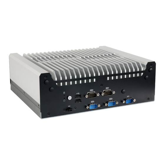
Product Overview Front View Antenna Holes HDD LED Power Button (w/ Status LED) Reset Button USB2.0 Type A Remote Switch COM4 COM2 COM1 COM3 Quick Reference | EC500-ADS... - Page 3 HDMI/DP port. The HDMI HDMI male connector shall align to the left of the port as illustrated here. The insertion is fairly effortless and please reframe from forcing the insertion to prevent damage. Quick Reference | EC500-ADS...
-
Page 4: Removing The Chassis Cover
The 12 screws on each side of the system are used to secure the cover to the chassis. Remove the screws and put them in a safe place for later use. Front View Rear View Left View Right View Quick Reference | EC500-ADS... - Page 5 Step 2: Lift the cover to open the system. Step 3: The board can be easily accessed after the chassis cover is removed. Quick Reference | EC500-ADS...
-
Page 6: Installing An Antenna
Connect the internal cable to the board's antenna connector, screw the antenna connector through the antenna hole with washers and nuts, and screw on the antenna as illustrated below. Antenna Chassis Wall Module Connector Cable Antenna Connector Washer Quick Reference | EC500-ADS... -
Page 7: Installing An M.2 Card
M.2 Modules: M.2 B Key & M.2 E Key M.2 Module: M.2 M Key Remove four screws and put them in a safe place for later use. After removing the screws, gently pull the SSD slot out of the system. Quick Reference | EC500-ADS... - Page 8 Remove four mounting screws and put them in a safe place for later use. Disassemble the heat dissipation plate to access the M.2 M Key. M.2 M Key Quick Reference | EC500-ADS...
- Page 9 3. Locate the M.2 socket on the system board 4. Make sure the notch on card is aligned to the key on the socket. 5. Make sure the standoff screw is removed from the standoff. M.2 Module M.2 Socket Stand-off Notch Quick Reference | EC500-ADS...
- Page 10 Screw tight the card onto the stand-off with a screw driver and a stand-off screw until the gap between the card and the stand-off closes up. The card should be lying parallel to the board when it’s correctly mounted. Quick Reference | EC500-ADS...
- Page 11 Installing Micro SIM Card Step 1: Step 2: Slide the cover to unlock. Lift the cover. Step 3: Step 4: Orient the SIM card and place it into the socket. Close the cover and slide the cover to lock. Quick Reference | EC500-ADS...
-
Page 12: Mounting Option
Locate the mounting holes on the bottom of the system as shown in the photo. Screw on the two brackets onto the system with six screws as illustrated below. Wall Mount Bracket Wall Mount Bracket Quick Reference | EC500-ADS... - Page 13 DFI reserves the right to change the specifications at any time prior to the product's release. This QR may be based on the product’s revision. For more documentation and drivers, please visit the download page at www.dfi.com/ downloadcenter, or via the QR codes to the right.
Need help?
Do you have a question about the EC500-ADS and is the answer not in the manual?
Questions and answers