
Subscribe to Our Youtube Channel
Related Manuals for GMI D1061S


Summary of Contents for GMI D1061S
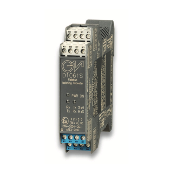
- Page 1 D1061S INSTRUCTION MANUAL RS422/RS485 Fieldbus Isolating Repeater Din-Rail Model D1061S D1061 - RS422 / RS485 Fieldbus Isolating Repeater ISM0068-12...
-
Page 2: Technical Data
Characteristics General Description: The single channel DIN Rail RS422 / RS485 Fieldbus Isolating Repeater type D1061S is used to separate Intrinsically Safe RS422 / RS485 equipment located in Hazardous Area from a RS232 / RS422 / RS485 controller located in Safe Area. Transmission speed is DIP-switch adjustable from 1.2 Kbit/s up to 1.5 Mbit/s. -
Page 3: Terminal Block Connections
Ordering information Model: D1061S Power Bus enclosure Front Panel and Features Input/Output from Zone 0 (Zone 20), Division 1, installation in Zone 2, Division 2. RS422 / RS485 Hazardous Area I.S. Signal. RS232 / RS422 / RS485 Safe Area Signal. - Page 4 Parameters Table In the system safety analysis, always check the Hazardous Area/Hazardous Locations devices to conform with the related system documentation, if the device is Intrinsically Safe check its suitability for the Hazardous Area/Hazardous Locations and gas group encountered and that its maximum allowable voltage, current, power (Ui/Vmax, Ii/Imax, Pi/Pi) are not exceeded by the safety parameters (Uo/Voc, Io/Isc, Po/Po) of the D1061 series Associated Apparatus connected to it.
-
Page 5: Function Diagram
CLASS II, DIVISION 1, GROUPS E, F, G, CLASS III, DIVISION 1, GROUPS A, B, C, D T-Code T4, CLASS I, ZONE 2, GROUP IIC T4 CLASS I, ZONE 0, GROUP IIC MODEL D1061S Supply 24 Vdc IN/OUT RS485 IN/OUT RS485... - Page 6 CLASS II, DIVISION 1, GROUPS E, F, G, CLASS III, DIVISION 1, GROUPS A, B, C, D T-Code T4, CLASS I, ZONE 2, GROUP IIC T4 CLASS I, ZONE 0, GROUP IIC MODEL D1061S Supply 24 Vdc RS485 Field Devices...
- Page 7 CLASS II, DIVISION 1, GROUPS E, F, G, CLASS III, DIVISION 1, GROUPS A, B, C, D T-Code T4, CLASS I, ZONE 2, GROUP IIC T4 CLASS I, ZONE 0, GROUP IIC MODEL D1061S Supply 24 Vdc RS485 Field Devices...
-
Page 8: Operation
Warning D1061 is an isolated Intrinsically Safe Associated Apparatus installed into standard EN50022 T35 DIN Rail located in Safe Area/ Non Hazardous Locations or Zone 2, Group IIC, Temperature Classification T4, Class I, Division 2, Groups A, B, C, D, Temperature Code T4 and Class I, Zone 2, Group IIC, IIB, IIA Temperature Code T4 Hazardous Area/Hazardous Locations (according to EN/IEC60079-15, FM Class No. -
Page 9: Installation
Installation D1061 is a RS232/RS422/RS485 fieldbus isolating repeater housed in a plastic enclosure suitable for installation on T35 DIN Rail according to EN50022. D1061 unit can be mounted with any orientation over the entire ambient temperature range, see section “Installation in Cabinet” and "Installation of Electronic Equipments in Cabinet" Instruction Manual D1000 series for detailed instructions. - Page 10 Configuration Proper configuration is obtained using internal dip-switches. The user can configure the operating mode on both Hazardous and Safe side, as RS422, RS485, RS232 (RS232 is available only on Safe side), the baud rate of the communication from 1200 b/s to 1.5 Mb/s and the frame length of a byte, indicated as data size (7 or 8 bit), parity (none, even or odd) and number of stop bit (1 or 2).
- Page 11 Side A Panel View Dip switch configuration Message format Configuration Baud rate Serial Line Type Configuration Configuration Serial Line Type Configuartion Hazardous Area Serial Line Safe Area Serial Line RS422 RS422 or RS232 RS422 RS485 RS485 RS422 or RS232 RS485 RS485 Factory settings...
-
Page 12: Switch Positions
Baud rate Configuration Baud Rate 1.500.000 1.000.000 750.000 500.000 375.000 187.500 93.750 115.200 57.600 38.400 19.200 14.400 9.600 Factory settings 4.800 2.400 1.200 Side B Panel View Switch positions Termination Resistor Configuration (Hazardous Area) Termination Resistor Configuration Hazardous 250 Ω...
Need help?
Do you have a question about the D1061S and is the answer not in the manual?
Questions and answers