Table of Contents
Advertisement
Quick Links
Advertisement
Table of Contents

Related Manuals for GMI D6031S


Summary of Contents for GMI D6031S
- Page 1 D6031S - D6031D INSTRUCTION MANUAL SIL 3 Switch/Proximity Detector Repeater Transistor Open Collector Output, DIN-Rail and Termination Board, Models D6031S, D6031D D6031 - SIL 3 Switch/Proximity Detector Repeater Open Collector Output G.M. International ISM0214-2...
-
Page 2: Technical Data
Current consumption @ 24 V: 22 mA for 2 channels D6031D, 12 mA for 1 channel D6031S with short circuit input and transistor closed, typical. Power dissipation: 0.53 W for 2 channels D6031D, 0.30 W for 1 channel D6031S with 24 V supply voltage, short circuit input and transistor closed, typical. -
Page 3: Ordering Information
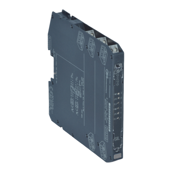
Ordering Information Power Bus and DIN-Rail accessories: Model: D6031 Connector JDFT049 Cover and fix MCHP196 1 channel Terminal block male MOR017 Terminal block female MOR022 2 channels Front Panel and Features SIL 3 according to IEC 61508:2010 Ed. 2 for Tproof =2 / 10 years (≤10% / >10 % of total SIF). SIL 2 according to IEC 61508:2010 Ed. - Page 4 Resistors R1 - R2 used with Termination voltage free contact required Power and board Fault Bus connector for line fault detection. Internal Dip switches programmable MODEL D6031S MODEL D5031S Supply 24 Vdc voltage free voltage free Proximity Contact Contact Out (SIL 3)
-
Page 5: Operation
On the section “Function Diagram” and enclosure side a block diagram identifies all connections. Identify the number of channels of the specific card (e.g. D6031S is a single channel model and D6031D is a dual channel model), the function and location of each connection terminal using the wiring diagram on the corresponding section, as an example: Connect 24 Vdc power supply positive at terminal “5”... - Page 6 Configuration D6031D used as double channel A configuration DIP switch is located on component side of pcb. This switch allows the configuration of input/output relationship, fault detection functions and operating mode. WARNING: dip-switch 6-7-8 must be set to “OFF” position. Dip switch factory settings.
- Page 7 Configuration D6031D used as duplicator or fault output A configuration DIP switch is located on component side of pcb. This switch allows the configuration of input/output relationship, fault detection functions and operating mode. WARNING: Terminals 9-10 must be shorted to set module as Duplicator or Fault Out. Dip-switch 3 must be set to “OFF”...
- Page 8 Configuration D6031S A configuration DIP switch is located on component side of pcb. This switch allows the configuration of input/output relationship, fault detection functions and operating mode. WARNING: Dip-switch 7-8 must be set to “OFF” position. Dip switch factory settings. All Switches are OFF Dip switch configuration 7-8 must be set to "OFF"...
- Page 9 Configuration DIP Switch factory settings (valid for D6031S and D6031D) SW1 SW2 SW7 SW8 D6031D (used as double channel) Configuration Summary Table WARNING: dip-switch 6-7-8 must be set to “OFF” position. Channel Channel Line fault detection IN/OUT Operation Disabled NO-NC or NC-NO...
Need help?
Do you have a question about the D6031S and is the answer not in the manual?
Questions and answers