
Related Manuals for GMI D6032S


Summary of Contents for GMI D6032S
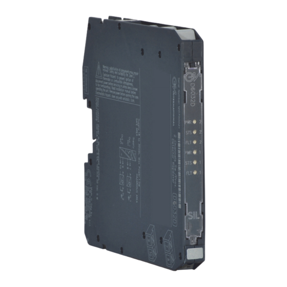
- Page 1 D6032S - D6032D INSTRUCTION MANUAL SIL 3 Switch/Proximity Detector Repeater Relay Output, Termination Board Models D6032S, D6032D D6032 - SIL 3 Switch/Proximity Detector Repeater Relay Output G.M. International ISM0405-0...
-
Page 2: Technical Data
Current consumption @ 24 V: 35 mA for 2 channels D6032D, 18 mA for 1 channel D6032S with short circuit input and relay energized, typical. Power dissipation: 0.85 W for 2 channels D6032D, 0.45 W for 1 channel D6032S with 24 V supply voltage, short circuit input and relay energized, typical. -
Page 3: Ordering Information
Ordering Information Model: D6032 1 channel 2 channels Front Panel and Features SIL 3 according to IEC 61508:2010 Ed. 2 for Tproof = 2 / 10 years (≤10% / >10 % of total SIF), considering 100 mA max contact current. ... - Page 4 Termination Relay contacts shown in voltage free contact required board connector de-energized position for line fault detection. Internal Dip switches programmable MODEL D6032S MODEL D5032S Supply 24 Vdc voltage free voltage free Proximity Contact Contact Out NO Contact (SIL 3)
-
Page 5: Operation
On the section “Function Diagram” and enclosure side a block diagram identifies all connections. Identify the number of channels of the specific card (e.g. D6032S is a single channel model and D6032D is a dual channel model), the function and location of each connection terminal using the wiring diagram on the corresponding section, as an example: For Model D6032S, in case of Proximity or Voltage free Contact, connect the wires at terminal “7”... - Page 6 Configuration D6032D used as double channel A configuration DIP switch is located on component side of pcb. This switch allows the configuration of input/output relationship, fault detection functions and operating mode. WARNING: dip-switch 6-7-8 must be set to “OFF” position. Dip switch factory settings.
- Page 7 Configuration D6032D used as duplicator or fault output A configuration DIP switch is located on component side of pcb. This switch allows the configuration of input/output relationship, fault detection functions and operating mode. WARNING: Terminals 9-10 must be shorted to set module as Duplicator or Fault Out. Dip-switch 3 must be set to “OFF”...
- Page 8 Configuration D6032S A configuration DIP switch is located on component side of pcb. This switch allows the configuration of input/output relationship, fault detection functions and operating mode. WARNING: Dip-switch 7-8 must be set to “OFF” position. Dip switch factory settings. All Switches are OFF Dip switch configuration 7-8 must be set to "OFF"...
- Page 9 Configuration DIP Switch factory settings (valid for D6032S and D6032D) SW1 SW2 SW7 SW8 D6032D (used as double channel) Configuration Summary Table WARNING: dip-switch 6-7-8 must be set to “OFF” position. Channel Channel Line fault detection IN/OUT Operation Disabled NO-NE or NC-ND...
Need help?
Do you have a question about the D6032S and is the answer not in the manual?
Questions and answers