
Related Manuals for GMI D5212Q


Summary of Contents for GMI D5212Q
- Page 1 D5212Q INSTRUCTION MANUAL SIL 2 Quadruple Repeater Power Supply DIN-Rail and Termination Board Model D5212Q D5212 - SIL 2 Quadruple Repeater Power Supply G.M. International ISM0361-3...
-
Page 2: Technical Data
General Description: The quadruple channel Repeater Power Supply D5212Q provides a fully floating DC supply for energizing conventional 2-wire 0/4-20 mA transmitters located in Hazardous Area, and repeats the current in Safe Area to drive a load in applications requiring SIL 2 level (according to IEC 61508:2010) in safety related systems for high risk industries. -
Page 3: Ordering Information
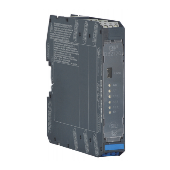
Ordering Information Power Bus and DIN-Rail accessories: Model: D5212 Connector JDFT050 Cover and fix MCHP196 Terminal block male MOR017 Terminal block female MOR022 4 channels Operating parameters are programmable from PC by the GM Pocket Portable Adapter PPC5092 via USB serial line and SWC5090 Configurator software. Front Panel and Features Input from Zone 0 (Zone 20) / Division 1, installation in Zone 2 / Division 2. -
Page 4: Parameters Table
Hazardous Area/Hazardous Locations and group encountered and that its maximum allowable voltage, current, power (Ui/Vmax, Ii/Imax, Pi/Pi) are not exceeded by the safety parameters (Uo/Voc, Io/Isc, Po/Po) of the D5212Q Associated Apparatus connected to it. Also consider the maximum operating temperature of the field device, check that added connecting cable and field device capacitance and inductance do not exceed the limits (Co/Ca, Lo/La, Lo/Ro) given in the Associated Apparatus parameters for the effective group. -
Page 5: Function Diagram
CLASS II, DIVISION 1, GROUPS E, F, G, CLASS III, DIVISION 1, GROUPS A, B, C, D T-Code T4, CLASS I, ZONE 2, GROUP IIC T4 CLASS I, ZONE 0, GROUP IIC MODEL D5212Q Common positive connection Alarm Out 2 Wire Tx... -
Page 6: Operation
Operation The quadruple channel Repeater Power Supply D5212Q provides a fully floating DC supply for energizing conventional 2-wire 0/4-20 mA transmitters located in Hazardous Area, and repeats the current in Safe Area to drive a load in applications requiring SIL 2 (according to IEC 61508:2010) in safety related systems for high risk industries. -
Page 7: Configuration Parameters
Configuration parameters: Screenshots: The SWC5090 is able to continuously scan the module and display the real-time values on screen. Note that while the module is being monitored, configuration screens are disabled. The display shows all the monitored parameters: Input: represents the value read from field. ... - Page 8 Configuration parameters: Screenshots: ALARM: Type: None: alarm is disabled Low: alarm is triggered when input descends below “Low Set” High: alarm is triggered when input ascends above “High Set” Window: alarm is triggered below “Low Set” and above “High Set” Alarm lock: alarm is inhibited until source ascends above or descends below the configuration parameters, and then, it behaves as standard configuration.
- Page 9 Supported ModBus Parameters: ModBus parameters details: Param. Description Notes Type (11) G.M. Factory Code Instrument Code Option Code Identification Supported ModBus Baudrates Data Hardware Release Index Baudrate Software Release 5 to 15 Reserved 4800 Modbus Address 9600 Communication Modbus Baudrate Data 19200 Modbus Format...
- Page 10 Supported ModBus Parameters: ModBus parameters details: Param. Description Notes Type (11) Output3 Under Range (Low 16 bits) Output3 Under Range (High 16 bits) Output3 Over Range (Low 16 bits) Output3 Over Range (High 16 bits) Output3 Fault Current (Low 16 bits) Output3 Fault Current (High 16 bits) Output3 Fault Mask Output3 InputA Selector...
Need help?
Do you have a question about the D5212Q and is the answer not in the manual?
Questions and answers