
Related Manuals for GMI D6036S


Summary of Contents for GMI D6036S
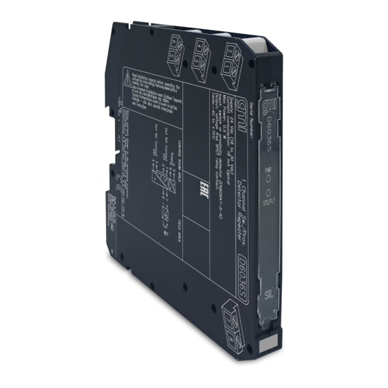
- Page 1 D6036S - D6036D INSTRUCTION MANUAL SIL 2 Switch/Proximity Detector Repeater, Relay Output DIN-Rail Models D6036S, D6036D D6036 - SIL 2 Switch/Proximity Detector Repeater, Relay Output G.M. International ISM0407-0...
-
Page 2: Technical Data
IEC 61508:2010 Ed. 2) in safety related systems for high risk industries. The unit can be configured for switch or proximity detector (EN60947-5-6, NAMUR), NO or NC and for NE or ND SPST (D6036D) or SPDT (D6036S) relay output contact. - Page 3 Front Panel and Features SIL 2 according to IEC 61508:2010 Ed. 2 for Tproof = 4 / 20 years (≤10% / >10 % of total SIF) for D6036S and D6036D. PFDavg (1 year) 2.25 E-04, SFF 70.87 % for D6036S.
- Page 4 Relay contact shown in de-energized position. voltage free contact required Power and Terminals 1-2 and 3-4 open. for line fault detection. Fault Bus MODEL D5036S MODEL D6036S Supply 24 Vdc voltage free voltage free Proximity Contact Contact Out NO Contact (SIL 2)
- Page 5 For Model D6036D in addition to channel 1 connections above, connect terminal “9” for positive and “10” for negative on channel 2. Connect SPDT (D6036S) or SPST (D6036D) relay contacts checking the load rating to be within the contact maximum rating (4 A 250 Vac 1000 VA, 4 A 250 Vdc 120 W resistive load).
- Page 6 Configuration D6036D A configuration DIP switch is located on component side of pcb. This switch allows the configuration of input/output relationship, fault detection functions and operating mode. Dip switch factory settings. All Switches are OFF Dip switch configuration Line fault Disabled Setting detection...
- Page 7 Output Input Output NO-ND or NC-NE For SIL Application Configuration DIP Switch factory settings (valid for D6036S and D6036D) SW1 SW2 SW3 SW4 Note: SW3 and SW4 used only in D6036D. D6036D Configuration Summary Table Channel Channel Line fault detection...
Need help?
Do you have a question about the D6036S and is the answer not in the manual?
Questions and answers