
Subscribe to Our Youtube Channel
Related Manuals for Festo EXPT-95


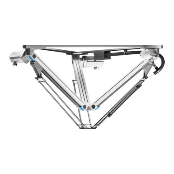
Summary of Contents for Festo EXPT-95
- Page 1 EXPT-95/120 Parallel kinematic system Operating instruc- tions 8159609 2021-08d [8159611]...
- Page 2 Translation of the original instructions...
-
Page 3: Table Of Contents
Demounting motor..........30 Festo — EXPT-95/120 — 2021-08d... - Page 4 Electrical data of the front unit ........39 Festo — EXPT-95/120 — 2021-08d...
-
Page 5: Safety And Requirements For Product Use
The product should only be installed by properly trained personnel in accordance with this description. The trained personnel must be familiar with: – the applicable instructions for accident prevention and occupational safety and – the documentation for the product. Festo — EXPT-95/120 — 2021-08d... -
Page 6: Transport And Storage
EXPT-...-T1 to T4 Storage temperature [°C] –10 … +60 Humidity 5 … 95, non-condensing 20 … 80, non-condensing Maximum shelf life 60 months Requirements for dry, solid and flat base storage location Tab. 2: Storage conditions Festo — EXPT-95/120 — 2021-08d... -
Page 7: Unpacking
Cut the foil parallel to the contour of the product with an appropriate tool. When cutting, make sure that the parallel kinematic system is not scratched or damaged. Then pull the foil up and away. Tab. 3: Unpacking Festo — EXPT-95/120 — 2021-08d... -
Page 8: Overview
- VHV front rear front - VVH front front rear - VVV front front front Protection against particles – Standard – P8 protected version Preset – Standard – S with calibration Tab. 4: Characteristics Festo — EXPT-95/120 — 2021-08d... -
Page 9: Function And Application
Variant P8 with protection against particles is functionally identical to the standard variants. Deviating from this are the toothed belt axes with the slide oriented upward so that abraded particles of the toothed belt remain in the axis and do not reach the working space. Festo — EXPT-95/120 — 2021-08d... -
Page 10: Design
Rod pair Interface housing Joint Manifold block (P8 variant is different) Toothed belt axis Protective conduit Earthing screw M6 (1x), mounting option (6x) Mounting frame Accessories Please select the corresponding accessories from our catalogue è www.festo.com/catalogue. Festo — EXPT-95/120 — 2021-08d... -
Page 11: Assembly
– The suspension of the parallel kinematic system is torsion-resistant and free of stress. – The bearing surface at the mounting corners is flat. – The mounting is sufficient for retaining the maximum forces è www.festo.com/catalogue. – The effects of mass and stiffness on positioning and path accuracy are taken into account. -
Page 12: Rack Mounting
Example of frame 2 Frame (example) 3 Mounting frame of parallel kinematic system 1 Slotted hole Tab. 6: Rack mounting NOTICE Deviations from the minimum requirements will cause increased wear or positioning inaccuracies in later operation. Festo — EXPT-95/120 — 2021-08d... -
Page 13: Types Of Mounting
Direct fastening to the frame with one screw per corner bracket. There is a central hole for this purpose at every bracket. – Make sure that the bearing surface lies in the area of the corner brackets. Tab. 8: Direct fastening variant 2 Festo — EXPT-95/120 — 2021-08d... -
Page 14: Slot Nut Mounting
If the slotted holes are used, the bearing surface of the screws is too small. Use the accompanying washers. 1 profile column, e.g. HMBS-80/80 2 Slot nut e.g. NST-HMV-8-2-M8 3 Screw e.g. M8x35 DIN 912 Tab. 10: Slot nut mounting variant 2 Festo — EXPT-95/120 — 2021-08d... - Page 15 Slot nut mounting variant 3 The additional user-specific brackets increase the tor- sional rigidity. 1 profile column, e.g. HMBS-80/80 2 Slot nut e.g. NST-HMV-8-2-M8 3 Screw e.g. M8x35 DIN 912 Tab. 11: Slot nut mounting variant 3 Festo — EXPT-95/120 — 2021-08d...
- Page 16 Slot nut mounting variant 4 The additional user-specific brackets increase the tor- sional rigidity. 1 profile column, e.g. HMBS-80/80 2 Slot nut e.g. NST-HMV-8-2-M8 3 Screw e.g. M8x35 DIN 912 Tab. 12: Slot nut mounting variant 4 Festo — EXPT-95/120 — 2021-08d...
-
Page 17: Preparations For Mounting
• Prepare the required mounting accessories for attachment to the frame. • In doing so, observe the instructions corresponding to the frame used and the intended method of mounting. Fig. 2: Preparations for mounting Rod pair Motor (optional) Toothed belt axis Mounting frame Festo — EXPT-95/120 — 2021-08d... - Page 18 • Fasten the parallel kinematic system to the frame in accordance with the specifications on the assembly drawing è 4.2 Rack mounting. • Observe the specifications for mounting è 4.3 Types of mounting. • Lock the screw connections. Festo — EXPT-95/120 — 2021-08d...
- Page 19 4. Lift the parallel kinematic system until the corner of the mounting frame at position 3 has a firm footing on the pallet. 5. Now turn the parallel kinematic system around position 3 into the vertical position. Festo — EXPT-95/120 — 2021-08d...
- Page 20 3. Have three persons raise the parallel kinematic system into the mounting position on the frame, where it can be attached by a fourth person. 4. The tightening torque for fastening the slot nuts is 10 Nm ± 20%. Festo — EXPT-95/120 — 2021-08d...
-
Page 21: Grippers And Suction Cups
5. When mounting again, make sure that the front unit’s original alignment to the rod pairs is not lost. Use the markings made before demounting. 4.5.2 EXPT-...-T1 to T4 For attaching grippers, suction cups, adapter kits and other accessories to the rotary drive è assembly instructions for the accessories. Festo — EXPT-95/120 — 2021-08d... -
Page 22: Installation
The illustration is an example and corresponds to variant EXPT-...-T4-HHH with rotary drive, pneumatic rotary through-feed and attachment position of the motors HH. You can expand the installation by ordering additional installation material as accessories è www.festo.com/catalogue. Description of the motor connections è Operating instructions of the motors. Festo — EXPT-95/120 — 2021-08d... -
Page 23: Connections At The Interface Housing
– Mount the motor cable 6 and encoder cable 3 for the rotary drive on the interface housing. – Install the sensor cable for the position sensing option SIEN of the rotary drive on the interface housing 2. Festo — EXPT-95/120 — 2021-08d... - Page 24 5 V supply GYPK Shield RDBU Tab. 15: Rotary drive encoder SIEN connection Port identification/signal Circuit diagram +10 … +30 V DC Operating voltage Switching output A (Out A) Tab. 16: Rotary drive position sensing Festo — EXPT-95/120 — 2021-08d...
-
Page 25: Motor Cables And Encoder Cables
• Specialist with knowledge of robotics and CODESYS • Knowledge of the handling and operation of the parallel kinematic system EXPT. For support during the commissioning phase: • Please contact your Festo contact person or via the internet (è www.festo.com). Festo — EXPT-95/120 — 2021-08d... -
Page 26: Operation And Diagnostics
Maintenance work Grease the bearing guide at the lubrication points 1 Lubrication interval every 6000 operating hours Lubricant Grease: Lub-KC1 (Festo) Position of the lubrica- tion points Tab. 17: Lubrication of the toothed belt axes Festo — EXPT-95/120 — 2021-08d... -
Page 27: Fault Clearance
2. Hold the parallel kinematic system in such a way that you can turn it freely. 3. Place the parallel kinematic system only on the mounting frame. NOTICE The parallel kinematic system can be set down without damage only after being turned over: • Prepare the required supporting surface (pallet). Festo — EXPT-95/120 — 2021-08d... - Page 28 4. The third person turns the parallel kinematic system by gripping corner 3 at the motor and axis and setting it down on the supporting surface, e.g. transport pallet. 5. Hold the parallel kinematic system firmly in the upright position by gripping on the motor, axis or mounting frame. Festo — EXPT-95/120 — 2021-08d...
- Page 29 – Make sure that the corner 3 on which the parallel kinematic system is standing is securely in place and cannot slide off the pallet. For later transport: 2. To secure the parallel kinematic system for transport, fasten it to the base plate with 6 self-tap- ping screws. Festo — EXPT-95/120 — 2021-08d...
-
Page 30: Demounting Motor
If necessary, also remove the coupling housing. When replacing: – Note that the motor must be mounted again in the same alignment as before è Assembly instruc- tions for axial kit. Fig. 11: Screws on the motor Festo — EXPT-95/120 — 2021-08d... -
Page 31: Demounting The Front Unit
After the first pair of rods is disconnected, the other two pairs can move, causing the front unit to lose its stability and position. To disconnect the front unit, proceed as follows: 1. Exhaust the supply port. Festo — EXPT-95/120 — 2021-08d... - Page 32 4. Position the front unit in an appropriate position which allows you to disconnect the other two pairs of rods from the front unit. 5. Disconnect the second and third pair of rods and remove the front unit. Festo — EXPT-95/120 — 2021-08d...
-
Page 33: Demounting The Protective Conduit
Tightening torque when reassembling: 0.25 Nm ± 20%. 4. Pull the protective conduit 1 out of the retainers. For installation of a new tubing holder (è Assembly instructions). Accessories and spare parts can be found at: (è www.festo.com). 8.1.5 Demounting a pair of rods... -
Page 34: Repair
• Note the information on mounting (è 4 Assembly) and demounting (è 8.1 Disassembly). Recommendation: – Contact our repair service. As a result, the required fine tuning and tests will be taken into special consideration. – Information about spare parts and aids can be found at: (è www.festo.com/spareparts). Festo — EXPT-95/120 — 2021-08d... -
Page 35: Technical Data
9.1.3 Pneumatic EXPT -120 Pneumatic port, rod loss detection Tubing with a nominal diameter of 4 mm Operating pressure [MPa] 0.2 … 0.8 [bar] 2 … 8 [psi] 29 … 116 Tab. 21: Pneumatic data Festo — EXPT-95/120 — 2021-08d... -
Page 36: Operating And Environmental Conditions
Compressed air in accordance with ISO 8573-1:2010 [5:4:1] Ambient temperature [°C] 0 … 40 Storage temperature [°C] –10 … +60 Humidity, non-condensing 5 … 95 20 … 80 Degree of protection IP40 Duty cycle Tab. 22: Operating and environmental conditions Festo — EXPT-95/120 — 2021-08d... -
Page 37: Dynamic
Maximum frame force horizontal ± 200 ± 215 vertical ± 325 ± 475 1) With a max. transient response of ± 0.5 mm 2) Only with calibrated system (order code S) Tab. 23: Dynamic data Festo — EXPT-95/120 — 2021-08d... -
Page 38: Technical Data - Front Unit
–0.9 … +10 [psi] – –13 … +145 Standard nominal flow rate [l/min] – Permissible leakage [l/h] – 1) At 0.6 MPa, 6 bar, 8.7 psi nominal pressure after 10 million cycles Tab. 25: Pneumatic data Festo — EXPT-95/120 — 2021-08d... -
Page 39: Electrical Data Of The Front Unit
Electrical data of the front unit EXPT Nominal voltage AC Max. output speed [rpm] Motor nominal current 0.31 0.31 0.74 0.74 Motor peak current 0.61 0.61 Motor nominal power 22.1 22.1 Duty cycle Tab. 26: Electrical data Festo — EXPT-95/120 — 2021-08d... - Page 40 Copyright: Festo SE & Co. KG 73734 Esslingen Ruiter Straße 82 Deutschland Phone: +49 711 347-0 Internet: © 2021 all rights reserved to Festo SE & Co. KG www.festo.com...
Need help?
Do you have a question about the EXPT-95 and is the answer not in the manual?
Questions and answers