Advertisement
Quick Links
ELGA-TB
Toothed belt axis
Instructions | Operating
8110947
201906f
[8110949]
Translation of the original instructions
1
Further applicable documents
All available documents for the product è www.festo.com/pk.
2
Safety
2.1
Safety instructions
–
Observe labelling on the product.
–
Prior to assembly, installation and maintenance work: Switch off power sup
ply, ensure that it is off and secure it against being switched back on.
–
Store the product in a cool, dry, UVprotected and corrosionprotected envir
onment. Ensure that storage times are kept to a minimum.
–
Observe tightening torques. Unless otherwise specified, the tolerance
is ± 20 %.
2.2
Intended use
The axis is intended to be used for positioning payloads in combination with tools
or as a drive when external guides are used.
The axis is only approved for slide operation.
Fig. 1 Slide operation
2.3
Training of qualified personnel
Installation, commissioning, maintenance and disassembly should only be con
ducted by qualified personnel. The qualified personnel must be familiar with
installation of electrical control systems.
3
Further information
–
Accessories è www.festo.com/catalogue.
–
Spare parts è www.festo.com/spareparts.
4
Service
Contact your regional Festo contact person if you have technical questions
è www.festo.com.
5
Product overview
5.1
Function
The axis converts the rotary motion of the mounted motor into a linear motion of
the slide. The torque of the motor is transmitted to the slide via the toothed belt
drive (TB). The linear movement of the slide is precisely guided by the guide. The
integrated cover strip prevents abraded particles from penetrating the immediate
vicinity of the drive. Sensors and displacement measuring system enable the
monitoring of end positions, reference position and intermediate position.
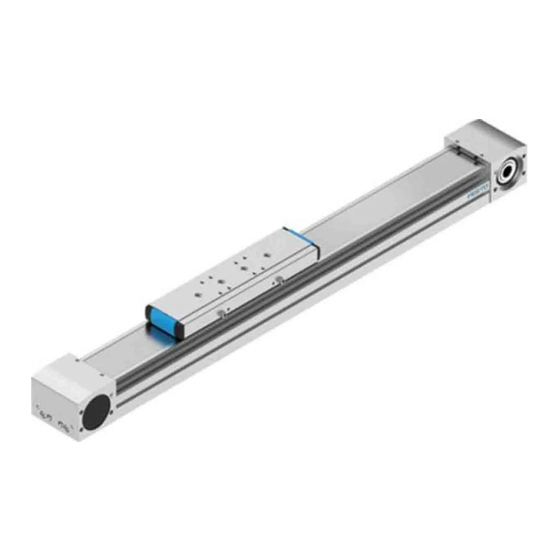
5.2
Product design ELGA-TB
Festo AG & Co. KG
Ruiter Straße 82
73734 Esslingen
Germany
+49 711 3470
www.festo.com
8110947
1 Drive hollow shaft
2 Threaded hole for motor mounting
kit and sealing air connection
3 Drive cover
4 Cover strip
5 Threaded and centring hole for
attachment element
6 Threaded hole for switch lug
7 Guide lubrication point
Fig. 2 Product design ELGATB (example ELGATBKF)
6
NOTICE!
Unexpected and unbraked movement of components
•
Secure moving components for transport.
Transport and storage conditions
1. Take product weight into account è 14 Technical data.
Weight > 25 kg: transport with a suitable hoist (crossbrace) or with two per
sons.
2. Consider axis centre of gravity.
3. Comply with maximum permitted support clearances when attaching trans
portation aids è 14.2 Characteristic curves.
4. Store and transport the product in its original packaging.
5. Store product in a cool, dry, shaded and corrosion protected environment.
6. Store product in ambient conditions without oils, greases and degreasing
vapours.
7. Ensure short storage times.
7
7.1
CAUTION!
For vertical or slanted mounting position: when power is off, moving parts can
travel or fall uncontrolled into the lower end position.
Injury due to impacts or crushing.
•
Bring moving parts of the product into a safe end position or secure them
against falling.
7.2
Protection of the cover strip
The cover strip is equipped with a protective cover to prevent damage. This pro
tective cover must be removed and disposed of before commissioning. After
removing the protective cover, mechanical damage and contamination of the cov
er strip must be avoided.
1. Open the packaging.
2. Remove all transport materials (e.g . foils, caps, cardboard boxes).
3. Remove the axis from the packaging and place it on the mounting surface.
Comply with maximum permitted support clearances when attaching trans
portation aids è 14.2 Characteristic curves.
4. Dispose of packaging and transport materials è 13 Disposal.
Product design
Transport and storage
Mounting
Safety
Unpack product
8 Slide
9 Shaft cover
10 Slot for sensor
11 Slot for profile mounting, slot nut
and sensor bracket
12 Slot for slot nut
13 Profile
14 Threaded and centring hole for
foot mounting
Advertisement

Subscribe to Our Youtube Channel
Related Manuals for Festo ELGA-TB


Summary of Contents for Festo ELGA-TB
- Page 1 Service Injury due to impacts or crushing. Contact your regional Festo contact person if you have technical questions • Bring moving parts of the product into a safe end position or secure them è www.festo.com.
- Page 2 2. Remove the sealing air plug screw from the threaded hole. – No collision in the movement space of the attachment component with motor, 3. Fasten motor mounting kit, observe instructions è www.festo.com/sp. mounting and sensor components. 4. Fasten the motor without tension. Support large and heavy motors.
-
Page 3: Operation
Carry out a homing run after every motor mounting in order to establish the – Prevention of contamination in the slots. absolute reference between the motor encoder and the reference mark. 1. Select accessories è www.festo.com/catalogue. 2. Mount mechanical end position protection: – Mount shock absorber retainer. - Page 4 Oil: Elkalub VP 916, – ELGATBKF: – Periodic check: every 500 km. ChemieTechnik, rollerbearing 2. If there is visible wear on the toothed belt: send the axis to Festo or contact Vöhringen grease LUBKC1 è www.festo.comFesto Service. – ELGATBKFF1: Elkalub VP 874, ChemieTechnik,...
- Page 5 Tab. 10 Overview of fault clearance 1850 3050 6890 11000 11.2 Repair – Observe the information for dismantling è 12 Disassembly – Send axis to Festo repair service. 1150 – Information about spare parts and accessories 1150 è www.festo.com/spareparts. ELGATB...RF, ELGATB...RFS 2000 – Disassembly 2000 –...
- Page 6 Fig. 9 ELGATBKF, support distances L as a function of force Fy 3.29 5.17 10.8 – Tab. 12 Materials and weight 14.2 Characteristic curves Support distance ELGA-TB-G/KF/RF-50/70/80/120/150 Maximum permissible support distance L (without profile mounting MUE/central support EAHF) as a function of force Fy/Fz with a maximum deflection of 0.5 mm.
- Page 7 ELGATBKF80F1 ELGATBRF80F1 Fig. 12 ELGATBKFF1, support distances L as a function of force Fz Fig. 16 ELGATBRFF1, support distances L as a function of force Fz Velocity ELGA-TB-G/KF/RF-50/70/80/120/150 ELGA-TB-RF-70/80/120 Velocity v as a function of the rotational speed n. 2400...
- Page 8 ELGA-TB-G-... 1000 1500 2000 2500 3000 3500 n [1/min] ELGATBG70 ELGATBG120 ELGATBG80 Fig. 17 ELGATBG, velocity v as a function of the rotational speed n ELGATBKF70 ELGATBKF120 ELGATBKF80 ELGATBKF150 Fig. 18 ELGATBKF, velocity v as a function of the rotational speed n ELGA-TB-RF-...
Need help?
Do you have a question about the ELGA-TB and is the answer not in the manual?
Questions and answers