
Related Manuals for Festo ELGC-BS-KF


Summary of Contents for Festo ELGC-BS-KF
- Page 1 ELGC-BS-KF Spindle axis Instructions | Operat- 8095590 8095590 2018-08c [8095592]...
- Page 2 Translation of the original instructions Festo — ELGC-BS-KF — 2018-08c...
-
Page 3: Table Of Contents
Mounting........................6 Preparation........................6 Mounting........................7 Attachment........................7 Mounting accessories....................8 Commissioning......................9 Service..........................11 Cleaning........................12 Fault clearance......................13 Disassembly........................ 14 Disposal........................14 Technical data......................15 13.1 Technical data, mechanical................... 15 13.2 Technical data, characteristic curves................17 Festo — ELGC-BS-KF — 2018-08c... -
Page 4: Further Applicable Documents
The qualified personnel must be familiar with installation of electrical control systems. Further information – Accessories è www.festo.com/catalogue. – Spare parts è www.festo.com/spareparts. Service Contact your regional Festo contact person if you have technical questions è www.festo.com. Festo — ELGC-BS-KF — 2018-08c... -
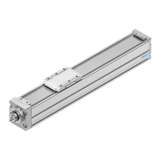
Page 5: Product Overview
8 Sealing air connection 4 Slide 9 Slot for sensor bracket 5 Thread/centring holes for attachment com- 10 Slots for attachment ponents Fig. 2 Product design ELGC-BS-KF Transport NOTICE! Unexpected and unbraked movement of components • Secure moving components for transport. -
Page 6: Mounting
Preparation – Unscrew screws and threaded pins only when requested. – Select the motor and motor mounting kit from Festo è www.festo.com/catalogue. When using other motors: observe the limit values for forces, torques and speeds è 13 Technical data. – When mounting the motor: follow the instruction manual for the motor mounting kit. -
Page 7: Mounting
1. Position the attachment component. Keep the tilt moment resulting from the force (parallel to the axis of movement) and lever arm as small as possible. 2. Avoid collisions of the mounting part and payload with other attachments. Festo — ELGC-BS-KF — 2018-08c... -
Page 8: Mounting Accessories
If proximity sensors are used as reference switches: • Use proximity sensors that correspond to the input of the controller being used. In case of inductive proximity sensors: use a switch lug è Assembly instructions of the accessor- ies. Festo — ELGC-BS-KF — 2018-08c... -
Page 9: Commissioning
Commissioning WARNING! Risk of injury due to unexpected movement of components. • Protect the positioning range from unwanted intervention. • Keep foreign objects out of the positioning range. • Perform commissioning with low dynamic response. Festo — ELGC-BS-KF — 2018-08c... - Page 10 Moving mass – Mounting position • When designing the spindle axis, use the Festo engineering software PositioningDrives è www.festo.com. NOTICE! Block-shaped acceleration profiles (without jerk limitation) cause high peaks in the drive force that can lead to an overloading of the drive. Due to overshooting effects, positions outside of the permiss- ible range may also occur.
-
Page 11: Service
The maximum permissible reversing backlash is 0.2 mm. Checking the cover strip • Check the cover strip after every 2000 km of operating distance. Waves on the cover strip are a sign of wear on the belt reversal device. Festo — ELGC-BS-KF — 2018-08c... -
Page 12: Cleaning
4. Tighten the screws. Tightening torque: size 32/45: 0.2 Nm; size 60/80: 0.8 Nm. If the cover strip can no longer be retensioned: • Replace belt reversal devices and covering è www.festo.com/spareparts. Cleaning Do not clean the guide elements (e.g. guide rails). •... -
Page 13: Fault Clearance
Loads too high. Reduce load mass/torques. Retaining screws on tool are too Observe the screw-in depth long. 7.3 Attachment. è The reversing backlash is too Wear Replace axis large ( 9 Service). www.festo.com/catalogue. è è Festo — ELGC-BS-KF — 2018-08c... -
Page 14: Disassembly
1. Observe transport information è 6 Transport. 2. Remove motor cables and mounting components. Information about spare parts and accessories è www.festo.com/spareparts. Disposal ENVIRONMENT! Send the packaging and product for environmentally sound recycling in accordance with the current regulations è www.festo.com/sp. -
Page 15: Technical Data
2nd degree of surface torque 38 x 10 140 x 10 441 x 10 1.37 x 10 45 x 10 170 x 10 542 x 10 1.66 x 10 Max. permitted forces on the slide 1800 2700 Festo — ELGC-BS-KF — 2018-08c... - Page 16 Guide, screws, ball bearings, Steel spindles, cover strip Coverings Belt reversal Weight Zero stroke length [kg] 0.30 0.73 1.70 2.95 Per metre of stroke [kg] 1) PWIS = paint-wetting impairment substances Tab. 6 Materials and weight Festo — ELGC-BS-KF — 2018-08c...
-
Page 17: Technical Data, Characteristic Curves
Technical data 13.2 Technical data, characteristic curves Speed v and working stroke l Fig. 10 ELGC-BS-KF-32 Fig. 11 ELGC-BS-KF-45 Festo — ELGC-BS-KF — 2018-08c... - Page 18 Technical data Fig. 12 ELGC-BS-KF-60 Fig. 13 ELGC-BS-KF-80 Festo — ELGC-BS-KF — 2018-08c...
- Page 20 Copyright: Festo SE & Co. KG Ruiter Straße 82 73734 Esslingen Germany Phone: +49 711 347-0 Fax: +49 711 347-2144 Reproduction, distribution or sale of this document or communic- e-mail: ation of its contents to others without express authorization is service_international@festo.com...
Need help?
Do you have a question about the ELGC-BS-KF and is the answer not in the manual?
Questions and answers