Table of Contents
Advertisement
Quick Links
Advertisement
Table of Contents

Subscribe to Our Youtube Channel
Related Manuals for Festo EXCM-40


Summary of Contents for Festo EXCM-40
- Page 1 EXCM-40 Planar surface gantry Operating instruc- tions 8170167 2022-03b [8170169]...
- Page 2 Translation of the original instructions LOCTITE 243 is a registered trademark of its respective trademark holder in certain countries. ®...
-
Page 3: Table Of Contents
Earthing..............33 Festo — EXCM-40 — 2022-03b... - Page 4 13.6 Materials..............40 Festo — EXCM-40 — 2022-03b...
-
Page 5: Applicable Documents
The qualified personnel have skills and experience in dealing with electropneumatic (open-loop) control technology. Additional information – Contact the regional Festo contact if you have technical problems è www.festo.com. – Accessories and spare parts è www.festo.com/catalogue. Festo — EXCM-40 — 2022-03b... -
Page 6: Product Overview
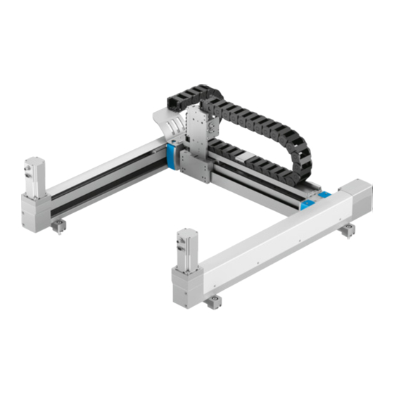
Product overview Product overview Design Fig. 1: EXCM-40-...-B example shown End cap Motor 2, optional X-axis 1 with energy chain Energy chain of the Y-axis End cap with toothed belt tensioning Y-axis device Y-axis slide X-axis 2 Motor 1, optional Mounting component –... -
Page 7: Functional Principle
Fig. 2: Functional principle Guide pulley for toothed belt Y-axis Toothed belt Y-axis slide The depicted directions of movement of the Y-axis slide refer to the directions of rotation of the motor of the functional principle. Festo — EXCM-40 — 2022-03b... -
Page 8: Transport
Locks in the packaging Transportation locks prevent uncontrolled movement of the product in the packaging during transport and installation. The product comes with the following labelled transportation locks: Transportation screws Cable binders Tab. 2: Identification of transportation locks Festo — EXCM-40 — 2022-03b... -
Page 9: Assembly
The mounting surface must have the following characteristics: – torsion-resistant and tension-free – sufficient strength for absorbing the maximum forces, sufficient flatness 6.1.3 Mounting points Fig. 3: Mounting holes, EXCM-40-... with 6 mounting components as example Mounting component Drive cover End cap Belt tensioning device... -
Page 10: Mounting Attachments
• Adhere to the specified limit values for flatness by taking appropriate measures. • Use adjustment kits. Slot nut Adjusting plate Hexagon head screw M6x30 (2x) Washer (2x) Socket head screw M8x40 (2x) Fig. 4: Mounting kit Festo — EXCM-40 — 2022-03b... -
Page 11: Adjusting Kit
The adjusting kits compensate for differences in height of the mounting surface of up to 5 mm. Slot nut Adjusting plate Hexagon head screw M6x30 (2x) Square nut (2x) Adjusting bolt Washer (2x) Socket head screw M8x40 (2x) Fig. 5: Adjusting kit Festo — EXCM-40 — 2022-03b... -
Page 12: Mounting
1. Make sure that all of the transport screws have been removed. 2. Attach a suitable hoist to the 4 transport lugs. Adjusting transport lugs to the direction of force of the hoist Fig. 7: Directions of lifting eye bolts Festo — EXCM-40 — 2022-03b... - Page 13 4. Slide the Y-axis (cross-brace) back and forth over the entire stroke of the X-axes. 5. Temporarily tighten the screws of all mounting kits with reduced tightening torque of 10 … 20 Nm. 6. Check the position of the motor cable outlets and adjust if necessary. Festo — EXCM-40 — 2022-03b...
-
Page 14: Aligning And Adjusting The Product
Energy chain of the X-axis tightening torque 1 Nm Profile cover of the X-axis 1. Unscrew the screws of the profile covers. If required, move the already loosened energy chain. 2. Remove the profile covers. Festo — EXCM-40 — 2022-03b... -
Page 15: Aligning And Adjusting X-Axis 1
5. Check the sideways tilt of the guide rail 1 in the area of the adjusting kit 2 with a precision spirit level 4. Setpoint value: £ 0.1 mm/m. Adjusting 6. Loosen one of the screws 7 on the adjusting kit. Festo — EXCM-40 — 2022-03b... - Page 16 11. Check the guide rail of X-axis 1 again for compliance with the limit values for flatness and tilt. Ä X-axis 1 is aligned and now forms the basis for the continuing alignment of the product. Festo — EXCM-40 — 2022-03b...
-
Page 17: Aligning And Adjusting X-Axis 2
X-axis 1 1. Setpoint value: £ 0.1 mm/m. Checking flatness 5. Make sure that the inspection base 3 lies correctly on the guide rail 1 of X-axis 2. Festo — EXCM-40 — 2022-03b... - Page 18 10. Screw the associated adjusting bolt 5 in or out (h = 6 … 11 mm). Use an open-ended spanner with a thickness of < 5 mm. Ensure that the screw-in depth of the screw is sufficient (with steel ³ 8 mm). Festo — EXCM-40 — 2022-03b...
-
Page 19: Aligning X-Axes Parallel With Each Other
6. Check both guide rails again for compliance with the limit values for the height offset, flatness and tilt. Eliminating warping in the product NOTICE Warping in the product Malfunctions due to increased wear and reduced service life. • Relieve warping. Festo — EXCM-40 — 2022-03b... -
Page 20: Checking The Toothed Belt Pretensioning
The toothed belt pretensioning can be checked with the profile cover of the X‑axis in place or removed. – At initial commissioning: demount the motors with holding brake. – After commissioning: release the holding brake. Festo — EXCM-40 — 2022-03b... - Page 21 Ä Distance dimension 144.4 mm (L11) is set for the test. 4. Align the probe 8 centrally on the toothed belt 7 under the belt tensioning setting piece 4. Do not touch the toothed belt during this process. Festo — EXCM-40 — 2022-03b...
-
Page 22: Setting The Toothed Belt Pretensioning
The toothed belt pretensioning is reduced during storage and operation. This is a normal process that must not be altered by retensioning the toothed belt. The reduced pretension is not suitable for evaluating the level of wear of the toothed belt. Festo — EXCM-40 — 2022-03b... - Page 23 4. Check the toothed belt pretensioning è 6.4.5 Checking the toothed belt pretensioning. Repeat this process until the measured value is within the specified frequency range. Festo — EXCM-40 — 2022-03b...
- Page 24 8. Fasten the energy chain to the retaining brackets with the bolts and nuts è 6.5.3 Mounting energy chain. Tightening torque 2.9 Nm Use LOCTITE 243 screw locking compound. 9. For motors with holding brake: Mount the X-axis drive motors. Festo — EXCM-40 — 2022-03b...
-
Page 25: Optional Work
5. Position the washers 6 under the socket head screws 7. 6. Fasten the mounting component 2 to the mounting surface with the socket head screws 7. 7. Tighten the socket head screws 7. Tightening torque 24 Nm Festo — EXCM-40 — 2022-03b... -
Page 26: Manually Moving The Y-Axis (Cross-Brace)
If mounting points are covered by the energy chain 3, it can be disconnected subject to the following points. Fig.9 1. Remove the screw 6 and the nut 5. 2. If necessary, also remove the screws 1 and the nuts 2 on the energy chain retaining bracket. 3. Remove the plate 4. Festo — EXCM-40 — 2022-03b... -
Page 27: Energy Supply
Assembly Energy supply The following pneumatic and electrical interfaces are available for connecting add-on elements. Fig. 10: Energy supply without attachment component Multi-pin plug distributor Bulkhead fitting, silver tubing Bulkhead fitting, black tubing Festo — EXCM-40 — 2022-03b... -
Page 28: Accessories
The proximity switch detects the position of the Y-axis (cross-brace) 2. A sensor mounting 1 is also required for mounting the proximity switch (not in scope of delivery). The sensor mounting and the proximity switch can be moved on the X-axis. Fig. 11: X-axis proximity sensor Festo — EXCM-40 — 2022-03b... -
Page 29: Y-Axis (Cross-Brace) Proximity Switch
Y-axis slide 3. The 2 switch lugs 1 for actuation of the proximity switch are mounted under the cover of the Y-axis (cross-brace) 2. The positions of the proximity switch and the switch lugs cannot be changed. Fig. 12: Y-axis (cross-brace) proximity switch Festo — EXCM-40 — 2022-03b... - Page 30 Assembly Mounting Fig. 13: Mounting proximity switch of Y-axis (cross-brace) Fig. 14: Mounting proximity switch of Y-axis (cross-brace) Festo — EXCM-40 — 2022-03b...
-
Page 31: Pneumatic Installation
21. Fasten the cables with cable binders 4 for strain relief between the energy chains. 22. Position the covering 3 and the retaining plate 8. 23. Tighten the screws 2. Tightening torque 1 Nm Pneumatic installation Description of the port patterns è 6.6 Energy supply. Festo — EXCM-40 — 2022-03b... -
Page 32: Electrical Installation
Unassigned for customer applications Unassigned for customer applications Unassigned for customer applications Unassigned for customer applications Unassigned for customer applications 1) In accordance with IEC 60757, at the loose cable end Tab. 5: Multi-pin plug distributor Festo — EXCM-40 — 2022-03b... -
Page 33: Earthing
The earthing point on the Y-axis slide is intended for earthing items such as an additional gripper o the attachment component. • Connect the open ends of the earthing cables to a central earthing point, e.g. in the control cabinet. Festo — EXCM-40 — 2022-03b... - Page 34 2. Place the small washer on top. 3. Tighten the hex nut. Tightening torque 4 Nm 4. Connect the open end of the earthing cable to a central earthing point, e.g. in the control cabinet. Festo — EXCM-40 — 2022-03b...
-
Page 35: Commissioning
• Commissioning may only be carried out by qualified personnel. • Experience with the installation and operation of electrical control systems is essential. • For support with commissioning, contact the regional contact person at Festo è www.festo.com. Additional information è www.festo.com/sp Homing •... - Page 36 Maintenance Lubrication points Fig. 18: Lubrication points Y-axis slide X-axis carriage Lubrication nipples on the guide carriage of Maintenance opening the Y-axis slide Y-axis (cross-brace) Lubrication nipples on the X-axis guide car- riage Festo — EXCM-40 — 2022-03b...
-
Page 37: Repair
6. Carry out steps 1. … 5. repeatedly. Repair Contact Festo Service if repairs are required è www.festo.com. Demounting 1. Traverse the Y-axis (cross-brace) to the mechanical end position opposite the motors. 2. Disconnect all of the electric cables and pneumatic hoses from the product. -
Page 38: Technical Data
[dB(A)] Degree of protection (in accord- IP40 ance with EN 60529) Duty cycle 1) Energy-equivalent A-rated sound pressure level at 1 m distance locally measured over the measurement area. Tab. 8: Operating and storage conditions Festo — EXCM-40 — 2022-03b... -
Page 39: Flatness
Guide rail of the X-axis Mounting component Limit values of the X-axis alignment [mm/m] £ 0.1 Flatness [mm/m] £ 0.1 Side tilt [mm/m] £ 0.1 Height offset [mm/m] £ 0.1 Parallelism Tab. 9: Limit values of the X-axis alignment Festo — EXCM-40 — 2022-03b... -
Page 40: Feed Constant
Drive covers and end caps Guide pulley Y-axis profile Slide X-axis and Y-axis covering Coupling Aluminium with elastomer ring gear Guide Steel Drive pinion Ball bearing Toothed belt PU with steel cord Tab. 12: Materials Festo — EXCM-40 — 2022-03b... - Page 42 Copyright: Festo SE & Co. KG 73734 Esslingen Ruiter Straße 82 Deutschland Phone: +49 711 347-0 Internet: © 2022 all rights reserved to Festo SE & Co. KG www.festo.com...
Need help?
Do you have a question about the EXCM-40 and is the answer not in the manual?
Questions and answers