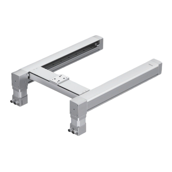
Festo EXCM-30 Mechanical Installation
Planar surface gantry
Hide thumbs
Also See for EXCM-30:
- Instructions manual (36 pages) ,
- Manual (84 pages) ,
- Repair instructions (52 pages)

Related Manuals for Festo EXCM-30


Summary of Contents for Festo EXCM-30
- Page 1 Planar surface gantry EXCM-30 Description Mechanical installation 8029292 1306NH [8025431]...
- Page 2 Essential or useful accessories. Information on environmentally sound usage. Text designations: • Activities that may be carried out in any order. 1. Activities that should be carried out in the order stated. – General lists. Festo – GDCE-EXCM-30-EN – 1306NH – English...
-
Page 3: Table Of Contents
............Festo – GDCE-EXCM-30-EN – 1306NH – English... - Page 4 Operating and environmental conditions ....... Festo – GDCE-EXCM-30-EN – 1306NH – English...
-
Page 5: Safety And Requirements For Product Use
Specific safety regulations can be found immediately before the task instructions. 1.1.2 Intended use The planar surface gantry EXCM-30 is designed for executing positioning tasks within machines or auto- mated systems with a higher-order controller and is to be used as follows: – in excellent technical condition –... -
Page 6: Requirements For Product Use
– the documentation for the product 1.2.3 Range of application and certifications Standards and test values which the product complies with and fulfils can be found in the technical data ( A.1 Technical data). Festo – GDCE-EXCM-30-EN – 1306NH – English... -
Page 7: Transport And Storage
Tab. 2.1 Checking the scope of delivery The scope of delivery of the planar surface gantry EXCM-30 is dependent on the order. 1. After unpacking, check whether the product corresponds to the version you ordered. 2. Check delivery for completeness. -
Page 8: Overview
Inside – T4 Outside Controller – Without controller – E… With controller, motor and encoder cables 1) Only in combination with motor type “-W-” (without motors) 3.1.1 Attachment position of motors Tab. 3.1 Festo – GDCE-EXCM-30-EN – 1306NH – English... -
Page 9: Attachment Position Of Motors
EXCM-30-…-B3 – Cable outlet inside EXCM-30-…-B4 – Cable outlet outside Motors on top: EXCM-30-…-T1 – Cable outlet at front EXCM-30-…-T2 – Cable outlet at rear EXCM-30-…-T3 – Cable outlet inside EXCM-30-…-T4 – Cable outlet outside Festo – GDCE-EXCM-30-EN – 1306NH – English... -
Page 10: Function And Application
The planar surface gantry is designed for executing positioning tasks within machines or automated systems with a higher-order controller. Functional principle The EXCM-30 planar surface gantry moves a slide in a 2-dimensional space by means of a shared toothed belt. Motor 1... -
Page 11: Design
Traverse of the Y-axis End cap Slide Profile of the X-axis Motor 1 (optional, 3.5 Motors) Drive cover of motor 2 Drive cover of motor 1 Motor 2 (optional, 3.5 Motors) Fig. 3.2 Festo – GDCE-EXCM-30-EN – 1306NH – English... -
Page 12: Attachment Position Of Motors Excm-30
Traverse of the Y-axis End cap Slide Motor 2 (optional, 3.5 Motors) Drive cover of motor 1 Profile of the X-axis Motor 1 (optional, 3.5 Motors) Drive cover of motor 2 Fig. 3.3 Festo – GDCE-EXCM-30-EN – 1306NH – English... -
Page 13: Motors
Motor attachment position underneath Motor attachment position on top (EXCM-30-…-B…) (EXCM-30-…-T…) 1) Represented is the option without motor brake with cable outlets to the front (EXCM-30-…-B1-ST-… or EXCM-30-…-T1-ST-…) Tab. 3.2 3.5.2 Motor variants Stepper motor without brake (EXCM-30-…-ST-…) Stepper motor with brake (EXCM-30-…-SB-…) -
Page 14: Interfaces
Signal trace N Brake (24 V) Signal trace N/ Brake (0 V) Vcc (5 V) – Tab. 3.5 3.6.2 Controller interfaces The interfaces of the controller are described in the EXCM “Commissioning” description. Festo – GDCE-EXCM-30-EN – 1306NH – English... -
Page 15: Mounting And Installation
Freely movable loads can result in injury to people and damage to the peripherals of the planar surface gantry. • Use a planar surface gantry without motor brake (EXCM-30-…-ST-…) exclusively in a horizontal mounting position. Design Mounting position EXCM-30-…-ST-…... -
Page 16: Dimensions Excm-30
H2 H3 Dimensions [mm] Size EXCM-30-…-ST-B… Stroke Stroke Stroke 58.8 70.4 ±0.5 X-axis Y-axis Y-axis EXCM-30-…-SB-B… 127.4 ±1.3 + 133 + 122 + 38 1) ( 3.1 Characteristics) Tab. 4.2 Festo – GDCE-EXCM-30-EN – 1306NH – English... -
Page 17: Dimensions Excm-30
H1 H2 H3 Dimensions [mm] Size EXCM-30-…-ST-T… Stroke Stroke Stroke 75.6 70.4 ±0.5 X-axis Y-axis Y-axis EXCM-30-…-SB-T… 127.4 ±1.3 + 133 + 122 + 38 1) ( 3.1 Characteristics) Tab. 4.3 Festo – GDCE-EXCM-30-EN – 1306NH – English... -
Page 18: Number Of Profile Mountings
4 profile mountings per profile at the profile ends, 1 additional profile mounting per profile in the 2 additional profile mountings per profile in the middle, optionally inside or outside. middle, in each case inside and outside. Festo – GDCE-EXCM-30-EN – 1306NH – English... -
Page 19: Mounting Holes For Profile Mountings
20.0 Min. 215.25 + 130 + 50.5 1) ( 3.1 Characteristics), Additional profile mounting on half the profile length with stroke X-axis › 500 mm ( 4.1.5 Number of profile mountings) Tab. 4.5 Festo – GDCE-EXCM-30-EN – 1306NH – English... -
Page 20: Mounting Of The Planar Surface Gantry
4. Tighten the screws slightly and align the profile. 5. After aligning the profile, tighten the screws to achieve complete attachment (tightening torque 1 Nm). Festo – GDCE-EXCM-30-EN – 1306NH – English... -
Page 21: Attachment
Procedure: The following graphics about the procedure for attachment of the planar surface gantry represent as an example the design EXCM-30-150-110-… with horizontal mounting posi- tion. 1. Prepare the mounting surface ( 4.1.2 Requirements of the mounting surface). - Page 22 4.2.1 Use of the profile mounting). 8. Tighten all screws of the profile mounting attachments (tightening torque 1 Nm). 9. Remove the transport safety measures of the planar surface gantry to complete the procedure. Festo – GDCE-EXCM-30-EN – 1306NH – English...
-
Page 23: Attachment Components And Accessories
(e.g. motors in the top attachment position) – the limit values defined in the technical data www.festo.com/catalogue) – the maximum screw-in depth of 5 mm – the maximum tightening torque of 1.5 ±0.3 Nm Festo – GDCE-EXCM-30-EN – 1306NH – English... -
Page 24: Setting End Stops Of The Y-Axis
To reduce the danger of collisions between attachment elements and planar surface gantry, the stroke of the Y-axis can be reduced by up to 10 mm on both sides by setting the end stops (threaded pins). 0 … 10 mm Threaded pin Slide Fig. 4.4 Festo – GDCE-EXCM-30-EN – 1306NH – English... -
Page 25: Motor Mounting
If you ordered the planar surface gantry without motor, the motor attachment kit compris- ing the entries 2, 3 and 4 (two each) is included. The coupling is not part of the scope of delivery. Festo – GDCE-EXCM-30-EN – 1306NH – English... -
Page 26: Third-Party Motors
If third-party motors are used, proximity sensors can be used to reference the planar surface gantry. A sensor mounting is available as an accessory for mounting the proximity sensor to the planar surface gantry ( www.festo.com/catalogue). Assembly instructions accompany the sensor mounting. Festo – GDCE-EXCM-30-EN – 1306NH – English... -
Page 27: Adapting The Position Of The Motor Cable Outlets
For planar surface gantries with motor brake, the brake must be released to dismantle the motors, e.g. with the help of the Festo Configuration Tools (FCT). Only in this way can the traverse of the Y-axis be shifted to make the clamping screw of the coupling accessible Fig. - Page 28 The following representations of the procedure for changing the position of the motor cable outlets represent an example for the design without motor brake and motor attach- ment position underneath (EXCM-30-…-ST-B…). The procedure applies correspondingly for deviating designs. 1. Move the traverse of the Y-axis until the 3.
-
Page 29: Commissioning
Note Commissioning should only be carried out by specially trained personnel. The following knowledge is required: – Knowledge of the Festo Configuration Tool (FCT) – Experience in installing and operating electrical control systems Commissioning is described in separate documents. For support in commissioning: •... -
Page 30: Maintenance And Care
A.1.6 Operating and environmental conditions). • When cleaning the system omit the guide elements in order to avoid impairing their lubrication. Otherwise, the lubrication of the guide elements will need to be renewed 6.2 Lubrication). Festo – GDCE-EXCM-30-EN – 1306NH – English... -
Page 31: Lubrication
1. Grease the marked bearing guides ( Fig. 6.1) on both sides at all lubrication holes. 2. Move the slide the complete travel distance during lubrication in order to distribute the grease evenly inside. Fig. 6.1 Festo – GDCE-EXCM-30-EN – 1306NH – English... -
Page 32: Disassembly And Repair
A.1 Technical data). • Handle the lubricants (greases, oils) in accordance with the applicable regulations governing health and safety and hazardous materials. • Observe the local regulations regarding waste disposal and the environment. Festo – GDCE-EXCM-30-EN – 1306NH – English... -
Page 33: A Technical Appendix
Planar surface gantry Guide Recirculating ball bearing guide Mounting position Type of mounting Profile mounting MUE-50 1) Motors with brake must be used in the case of vertical installation (EXCM-30-…-SB-…). A.1.2 Certifications Variant EXCM-30-…-E… CE marking (see declaration of conformity) To EU EMC Directive www.festo.com) -
Page 34: Product Weight
Repetition accuracy [mm] ±0.05 1) Vertical / horizontal mounting position. 2) These values must also be complied with during installation of third-party motors 3) At v=0.2 m/s and 45° diagonal travel Tab. A.5 Festo – GDCE-EXCM-30-EN – 1306NH – English... -
Page 35: Operating And Environmental Conditions
Operating and environmental conditions Size Ambient temperature [°C] +10 … +45 Protection class IP20 Storage temperature [°C] –10 … +60 Air humidity 0 … 90 (non-condensing) Maximum noise level [dB(A)] 55 Duty cycle Tab. A.8 Festo – GDCE-EXCM-30-EN – 1306NH – English... - Page 36 Copyright: Festo AG & Co. KG Postfach 73726 Esslingen Germany Phone: +49 711 347-0 Fax: +49 711 347-2144 e-mail: service_international@festo.com Reproduction, distribution or sale of this document or communica- Internet: tion of its contents to others without express authorization is www.festo.com...
Need help?
Do you have a question about the EXCM-30 and is the answer not in the manual?
Questions and answers