Table of Contents
Advertisement
Quick Links
Advertisement
Chapters
Table of Contents
Troubleshooting

Subscribe to Our Youtube Channel
Related Manuals for PREVOST X3-45 VIP 2017


Summary of Contents for PREVOST X3-45 VIP 2017
- Page 1 Owner’S MANUAL X3-45 VIP...
- Page 3 COACH MANUFACTURER OWNER’S MANUAL X3-45 VIP PA1625 Rev 2 November 2017...
- Page 4 PA1625 Featuring: GHG17 Motor Electrical Fan Drive New Electrical Architecture First edition: February 2017, Model-year 2017 starting from vehicle H-6180 EFFECTIVE DESCRIPTION DATE First Release Feb 2017 H6180 Starting and Stopping procedures: Revised rear start panel images & text June 2017 Prelim: J-6223, Section 5: Added Wheelchair Lift Option...
- Page 5 This manual, or portions thereof, cannot be to the proper operation of the vehicle. reproduced in any form whatsoever, in whole or in part, without the written consent of PREVOST For your own safety and to ensure prolonged CAR INC.
- Page 6 EDR is the same; i.e., they do not all record the same data elements. The EDR on this PREVOST vehicle records vehicle speed, engine RPM, time and date, plus a variety of pedal and switch positions, both before and after an "event." Sudden vehicle deceleration or the occurrence of certain other vehicle operational characteristics will define (trigger) an "event."...
- Page 7 Prevost does not collect any driver information. Prevost retains and uses this information to understand the operational use of your vehicle, to remotely tune your vehicle, and to help facilitate maintenance and vehicle improvements. To the extent allowed by law, Prevost reserves the right to access, use and control this information.
- Page 8 Foreword iv...
-
Page 9: Table Of Contents
Table of contents v SECTION 1 SAFETY PRECAUTIONS ....................1-1 SECTION 2 VEHICLE EXTERIOR ....................2-1 SECTION 3 VEHICLE INTERIOR ..................... 3-1 SECTION 4 CONTROLS AND INSTRUMENTS ................4-1 SECTION 5 OTHER FEATURES ...................... 5-1 SECTION 6 STARTING AND STOPPING PROCEDURES .............. 6-1 SECTION 7 SAFETY FEATURES AND EQUIPMENT .............. -
Page 11: Safety Precautions
Safety Precautions 1-1 SAFE OPERATING PRACTICES ........................ 2 DEFENSIVE DRIVING PRACTICES ......................2 OTHER PRECAUTIONS ..........................3... - Page 12 Safety Precautions Fuel is highly flammable and explosive. Do To ensure safe and reliable operation, heed the not smoke when refueling. Keep away from following safety precautions. open flames or sparks. SAFE OPERATING PRACTICES Do not run the engine or HVAC system with access doors left open.
- Page 13 Safety Precautions OTHER PRECAUTIONS CAUTION DANGER PRECAUTIONS ARE TO BE OBSERVED BEFORE WELDING TO MINIMIZE THE RISK Prior to working on a system inside the OF MAJOR AND COSTLY DAMAGES vehicle, make sure to cut electrical power and CAUSED TO THE VEHICLE ELECTRONIC air supply.
-
Page 15: Vehicle Exterior
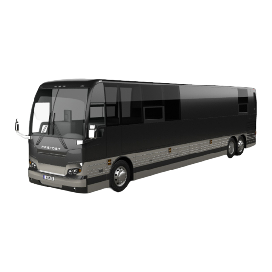
Vehicle Exterior ENGINE COMPARTMENT COMPONENTS ....................4 ENGINE COMPARTMENT R.H. SIDE DOOR ..................... 5 ENGINE COMPARTMENT REAR DOOR ....................5 EXHAUST AFTERTREATMENT SYSTEM ACCESS DOOR ..............6 RADIATOR DOOR ............................7 CATALYTIC CONVERTER ACCESS DOOR ....................7 CONDENSER COMPARTMENT (A/C) ......................8 EVAPORATOR COMPARTMENT ....................... - Page 16 Vehicle Exterior X3-45 VIP MOTORHOME EXTERIOR VIEW (TYPICAL) Engine air intake Rear-view mirror Engine compartment R.H. side door Reclining bumper Hinged rear fender Front electrical and service compartment Driver’s power window Baggage compartment Fuel filler door Evaporator or baggage compartment Condenser or baggage compartment Radiator door Entrance door...
- Page 17 Vehicle Exterior X3-45 VIP COMERCIAL USE VEHICLE TYPICAL EXTERIOR VIEW (FRONT SLIDE-OUT SHOWN) 18369 Engine air intake Rear-view mirror Engine compartment R.H. side door Front reclining bumper Hinged rear fender Front electrical and service compartment Driver’s power window Baggage compartment Fuel filler door Evaporator compartment Condenser compartment...
-
Page 18: Engine Compartment Components
Vehicle Exterior ENGINE COMPARTMENT COMPONENTS ENGINE COMPARTMENT FEATURING VOLVO D13 ENGINE 1. Diesel Oxidation Catalyst (DOC) & Diesel Particulate Filter (DPF) Assembly; 2. Transmission fluid dipstick; 3. Coolant fluid surge tank filler cap; 4. Coolant fluid surge tank sight glass; 5. -
Page 19: Engine Compartment R.h. Side Door
Vehicle Exterior Most serviceable parts may be accessed through exterior compartments. There may be slight differences in the location of parts and in the configuration of compartments between models, depending on options. ENGINE COMPARTMENT CURB SIDE DOOR The engine compartment R.H. side door provides access to the following (if equipped):... -
Page 20: Exhaust Aftertreatment System Access Door
Vehicle Exterior The door swings out to provide access to the WARNING following: Engine; Unless otherwise specified, do not run engine when the engine compartment rear door is Alternator(s); open. Close the engine compartment rear Compressor(s); door before starting the engine. Belt tension valve (refer to Care and EXHAUST AFTERTREATMENT Maintenance chapter);... -
Page 21: Radiator Door
Vehicle Exterior RADIATOR DOOR The engine radiator door gives access to the radiator electrical fans and power distribution box. RADIATOR DOOR opened WARNING WHEN THE ENGINE IS RUNNING… RADIATOR DOOR Cooling fans may activate at any moment. Open the engine compartment rear door to Keep hands away from cooling fans or keep access the engine radiator door release handle the radiator door closed. -
Page 22: Condenser Compartment (A/C)
Vehicle Exterior SCR CONVERTER ACCESS DOOR Filter dryer and moisture indicator; Receiver tank. To gain access to the catalytic converter, open the radiator door first. At the top of the radiator compartment, pull the catch connecting rod to unlock the catalytic access door and lift the door open. -
Page 23: Evaporator Compartment
Vehicle Exterior EVAPORATOR COMPARTMENT The HVAC (Heating, Ventilating and Air- Conditioning) evaporator blower and coolant heater compartment located this compartment. The compartment door release latch is located on the right side of the baggage compartment and to the left of the HVAC compartment door. Pull the release latch then slide your hand in the opening to depress the secondary lock and swing open. -
Page 24: Front Electrical And Service Compartment
2-10 Vehicle Exterior FRONT ELECTRICAL AND SERVICE COMPARTMENT To open the front electrical and service compartment door, pull the rod inside the vehicle, next to the driver’s power window or use the key to open from outside the vehicle. The front electrical service... -
Page 25: Reclining Bumper Compartment
Vehicle Exterior 2-11 release the latch, and then pull the door open. & Instruments" chapter. Pressurized cylinders assist the opening and closing of the baggage compartment doors and RECLINING BUMPER hold the doors open. COMPARTMENT To close, pull the door down by the handle rod. Complete the closing of the door by returning The front bumper can be tilted downward to give the operating handle to its initial position. -
Page 26: Entrance Door
2-12 Vehicle Exterior NOTE CAUTION The stepwell lights and entrance overhead light turn on as the door opens. Do not fill to more than 95% of the tank capacity. Do not "top off" the tank, doing so There are two ways of unlocking the entrance may result in fuel spillage when the fuel door from the inside. -
Page 27: Back-Up Camera
Vehicle Exterior 2-13 CAUTION Do not attach stick-on type convex mirror accessories to the heated mirror glass. This could impede uniform heat distribution on the mirror surface and could break the mirror glass. 110-120 VOLT CONNECTOR 06390 Another connector is used to connect the battery charger to a 120 VAC power source. - Page 28 This hitch must be used for recreational NOTE use only. minimum requirement trailer weighing up to 20,000 lbs when coupled to a 20,000 lb Prevost Trailer Hitch is as per the following: Trailer must comply with Federal Motor Carrier Safety Regulations 393.52 regarding trailer breaking capability.
-
Page 29: Vehicle Interior
Vehicle Interior DRIVER'S "DELIVERY" SEAT ........................2 DRIVER'S AND CO-PILOT'S SEATS - ISRI (OPTIONAL)................2 PNEUMATIC ISRI SEATS ............................2 ELECTRIC ISRI SEATS ............................2 DRIVER SEAT BELT ............................ 3 STEERING WHEEL ADJUSTMENT ......................4 SUNSHADES (BLINDS) ..........................4 INSIDE MIRROR ............................4 ADJUSTABLE HVAC REGISTERS ...................... -
Page 30: Driver's "Delivery" Seat
Vehicle Interior DRIVER'S "DELIVERY" SEAT Fore-and-aft (3)* Pull handle up and slide seat forwards or The driver's "delivery" seat is standard and legal backwards to adjust distance between seat and only for driving the vehicle on its initial delivery. dashboard. It is a conventional van seat equipped with tracks for fore and aft adjustments. -
Page 31: Driver Seat Belt
Vehicle Interior Fore-and-aft/Up-Down (2) Push switch towards dashboard to move seat NOTE forwards or back to move seat backwards. Pull switch up to raise seat or push switch down to The safety belt must be pulled out slowly and lower seat. continuously, otherwise it will lock the reel before the latch plate reaches the buckle. -
Page 32: Steering Wheel Adjustment
Vehicle Interior SPRING RELEASE SUNSHADE 23143 INSIDE MIRROR One (optional) mirror is located in the driver’s area, the central mirror allows the driver to see UNFASTENING SEATBELT in the central cabin aisle. 18029 STEERING WHEEL ADJUSTMENT ADJUSTABLE HVAC REGISTERS Push on the valve button with the left foot to The HVAC system has adjustable registers to unlock the steering wheel for tilt and telescopic control air flow. -
Page 33: Awning Windows
Vehicle Interior AWNING WINDOWS SLIDING WINDOWS To open or close an electrically-operated awning To open or close an electrically-operated sliding window, use the rocker switch button located on window, use the rocker switch button located on the wall, next to the window. After closing the the wall, next to the window. -
Page 35: Controls And Instruments
CRUISE CONTROL ............................ 11 Turning the system ON ........................11 Setting at a desired speed ........................11 PREVOST AWARE ADAPTIVE CRUISE BRAKING ................... 12 Turning the ACB system ON ....................... 13 Turning OFF the ACB system ......................13 Maintaining a set following distance ....................13 Driver warnings ............................ - Page 36 Controls and Instruments Traction Control System Mud/Snow Mode (option) ................23 Left and Right Sunshades ........................23 Docking/Cornering Lights ........................23 When the switch is set to CORNERING and the left or right turn signal is activated, the corresponding front beam will illuminate to increase lateral visibility................23 Fast Idle ...............................
- Page 37 Controls and Instruments CHECK Telltale light ..........................35 INFORMATION Telltale light ....................... 35 Acknowledging Messages ........................35 DRIVER INFORMATION DISPLAY ........................35 Selecting a menu ..........................36 To change settings ..........................36 Scrolling through the menus without using the steering wheel buttons ..........37 PICTOGRAMS DISPLAYED ON THE DRIVER INFORMATION DISPLAY (DID) ..........
- Page 38 Controls and Instruments DRIVER'S AREA LATERAL CONTROL PANEL 18563 1. Lateral console 2. DOT certification plate 3. Diagnostic Data Reader (DDR) receptacle 4. Foot operated steering wheel adjustment unlock air valve 5. Dashboard 6. Rear view TV monitor (optional) 7. Front service door unlocking pull-rod...
-
Page 39: Keys
Controls and Instruments KEYS The ignition switch doubles as the battery master switch. Any position other than OFF Four different key models are provided with the activates the battery electrical circuit. The vehicle: battery electrical circuit is also activated when the hazard switch is depressed. -
Page 40: Accessories
Controls and Instruments connected directly to the batteries can be REMOTE ENTRY TRANSMITTER activated. These are: the coolant heater and Hand held transmitters (key FOB) can be used water pump, the keyless entry system and anti- to control the keyless door lock system. theft alarm, the central locking system, entry lights electric horn and Driver Information Display (DID). -
Page 41: Transmission Control Pad (1)
CONTROL SWITCHES (2) Cruise Control Switch For operation of the cruise control, refer to “Regular Cruise Control” or “Prevost Aware Adaptive Cruise Braking” paragraph in this chapter 06701 Back-up Alarm Cancel Press down this switch to cancel the Back-Up Alarm. -
Page 42: Power Window Switch
Controls and Instruments Turn left pointer knob counterclockwise for Power Window Switch outside flat mirror adjustments and to the right Use this rocker switch to open or for convex mirror adjustments, then use the close the driver’s power window. joystick control to adjust the selected mirror’s viewing angle. -
Page 43: Parking Brakes Control Valve (7)
Controls and Instruments NOTE DANGER Prevost vehicles are designed to operate within specific weight load/ranges for each Do not drive the vehicle with the level low axle (GAW) and for total vehicle weight selector switch in any position other than OFF, (GVW). -
Page 44: Cigarette Lighter (9)
4-10 Controls and Instruments the DDR receptacle. A user's manual is supplied with the optional DDR. CIGARETTE LIGHTER (9) The DDR receptacle is located inside the Push lighter in to activate. When ready to use, it footwell, on the upper left side wall. will spring out automatically. -
Page 45: Cruise Control
Controls and Instruments 4-11 twisting and pulling the tamper seal to remove, release the SET button then remove foot from lifting the cover and pressing the red “FIRE” the accelerator pedal. This will set the vehicle button for more than half a second. After the cruise speed and store it in memory. -
Page 46: Prevost Aware Adaptive Cruise Braking
When the cruise rocker switch is released, the Braking Operator’s Manual (available on cruise control is completely shut off and the Prevost web site and included on the cruise speed setting is erased from the cruise Technical Publications CD) will assist in control memory. -
Page 47: Turning The Acb System On
ACB is turned on. In addition to the audible the set time gap remains the same for all set and visual warnings, when the ACB is turned on cruise speeds. Prevost’s default set time gap is and a cruise speed is set, the driver benefits 1.7 seconds. -
Page 48: Driver Warnings
4-14 Controls and Instruments Flashing red: Collision alert. The forward accelerates away, and the ACB system did not need to use the service brakes as it vehicle is to close to follow safely or a managed the intervention, the coach will metallic stationary object such as a stopped automatically accelerate back to the original or stalled vehicle in your lane of travel is... - Page 49 Controls and Instruments 4-15 Once the audible warning is given, the driver fade. For example, the use of ACB on downhill must increase the distance between the coach runs may cause this alert to be activated. It is and the vehicle ahead until the audible warning recommended that ACB be disengaged on stops or maneuver clear of the forward vehicle.
- Page 50 4-16 Controls and Instruments FOLLOWING DISTANCE ALERT CONDITION The Following Distance Alert feature is only available when the coach speed is greater than 37 mph (60 km/h), whether or not ACB is engaged. The forward vehicle is slowing down and the distance between your vehicle the coach and the forward vehicle is less than the set distance “Distance Alert”...
-
Page 51: Tire Pressure Monitoring System (Tpms)
FORWARD VEHICLE DETECTED telltale light The TPMS display is initially configured to define how many axles and running tires are present on the vehicle. For current Prevost vehicle models, there are two axle / tire configurations. ACB NOT AVAILABLE pictogram... -
Page 52: Operation
4-18 Controls and Instruments The TPMS display is also configured with Pre-Trip Check several other parameters, including threshold When one of the preconditions defined to start levels for the alarms. the pre-trip check is met, the TPMS display The TPMS display power supply turns OFF enters into a pre-trip check routine and the when the ignition key is switched OFF. - Page 53 Controls and Instruments 4-19 The switching to temperature does not take place either if there is an alarm of Temperature or Flat Tire. The switching to temperature works when the bottom message indicates either: Tire Pressure OK, Pressure Not Optimal non flashing or not all tires monitored non flashing.
- Page 54 4-20 Controls and Instruments inflate / deflate the tires to bring them back to their optimum target pressures. Scrolling through these menus is also available prior to departure. The display remains in this mode with the menus appearing at the bottom until the pre-trip check sequence starts again.
-
Page 55: Dashboard
Controls and Instruments 4-21 DASHBOARD DASHBOARD 06754_vip L. H. Dashboard Panel Instrument Cluster Vehicle Clearance Information R. H. Dashboard Panel HVAC Control Unit Air Vents Brightness Control Diver Information Display (DID) Ignition Switch Tire Pressure Monitoring System (TPMS) Display... -
Page 56: Control Switches
4-22 Controls and Instruments CONTROL SWITCHES Fog Lights High quality laser-engraved switches are used to Optional halogen fog lights provide better visibility control many of the features of the vehicle. Many switches have an embedded witness LED to precipitation. They improve close inform the driver at a glance which features are range visibility and provide added active. -
Page 57: Traction Control System Mud/Snow Mode (Option)
Controls and Instruments 4-23 Windshield Upper Section De-icing CAUTION Optionally on Entertainers only, the Do not attempt to raise or lower these shades vehicle may be equipped with a de- manually. Damage to the electric motor or roller icing system in the windshield upper mechanism could result. -
Page 58: Engine Stop Override (With Automatic Fire Detection And Suppression System)
4-24 Controls and Instruments Engine Stop Override (with Automatic Fire Engine Brake (optional) Detection and Suppression System) Press the Engine Stop Override The vehicle’s engine brake is by switch on the dashboard or the default set to automatic (AUTO Delay Engine Stop switch on the mode vehicles AFSS protection panel to delay the... -
Page 59: R.h. Dashboard Panel
Controls and Instruments 4-25 R.H. DASHBOARD PANEL Entrance Door Power Window Use the rocker switch to open or close the power window in the entrance door. The switch for the driver’s power window is on the Lateral control panel. 06338 Entrance Door Switch Use this rocker switch located on the dashboard’s R.H. -
Page 60: Heating Mode Indicator
4-26 Controls and Instruments Heating Mode Indicator Illuminates when system is heating. 22135 Cooling Mode Indicator SMALL HVAC SYSTEM CONTROL MODULE 22333 The vehicle is slightly pressurized by the central Illuminates when system is cooling. HVAC system to prevent dust and moisture from entering. -
Page 61: Windshield Defogger
Controls and Instruments 4-27 NOTE Temperature Degree Selector Upon starting of the vehicle, when the ambient Toggles between Fahrenheit temperature is very cold and so is the inside of Celsius units (Driver’s HVAC unit must the vehicle, the HVAC control module will be turned ON). -
Page 62: Instrument Cluster
4-28 Controls and Instruments INSTRUMENT CLUSTER 06727 1. Tachometer 7. Driver Information Display (DID) 2. Telltale lights 8. Oil pressure indicator 3. Speedometer 9. DEF level (Diesel Exhaust Fluid) indicator 4. Front brake air pressure (secondary) 10. Engine coolant temperature 5. -
Page 63: Analog Indicators
Indicates the vehicle speed in miles per hour (mph) and kilometers per hour (km/h). The LEDs above the instrument work in conjunction with AWARE Adaptive Cruise Braking (ACB) system. Refer to “Prevost AWARE Adaptive Cruise Braking” paragraph. 06729 Turbo Boost Pressure (PSI) Indicates the turbo boost pressure in psi. - Page 64 4-30 Controls and Instruments checked. If the temperature remains below or exceeds the normal temperature range, the cooling system should be checked for problems. STOP telltale light Engine Oil Pressure (PSI) Indicates the engine oil pressure in psi. When the oil pressure is too low, the stop telltale light turns on, an audible alarm sounds and a message appears on the DID.
- Page 65 Controls and Instruments 4-31 Rear Brake Air Pressure (PSI) – Primary System Indicates the rear brake air system pressure in psi. The normal operating pressure is from 122 to 140 psi. A low air pressure indicator led illuminates when the rear (primary) air system pressure drops below 75 psi.
-
Page 66: Telltale Lights
4-32 Controls and Instruments TELLTALE LIGHTS The telltale lights illuminate during 5 seconds at the start of every ignition cycle as a light bulb check. STOP Indicates that a serious problem has been detected. Immediately park the coach in a safe place and stop the engine. -
Page 67: Cruise Control
Controls and Instruments 4-33 CRUISE CONTROL Indicates that the cruise control is enabled. CRUISE CONTROL SET SPEED Indicates that a cruising speed is set and stored in the memory. HIGH EXHAUST SYSTEM TEMPERATURE (HEST) Illuminates to notify the driver of potentially hazardous exhaust gas temperature at the 06740_A exhaust system diffuser. -
Page 68: Flat Tire (With Optional Tire Pressure Monitoring System)
4-34 Controls and Instruments FLAT TIRE (WITH OPTIONAL TIRE PRESSURE MONITORING SYSTEM) Illuminates when a tire pressure is 25% below the target tire pressure. 06740_F HILL START ASSIST Indicates a malfunction of the hill start assist function. This function might not be available. -
Page 69: Check Telltale Light
Controls and Instruments 4-35 (see “Acknowledging Messages” messages STOP, CHECK AND INFORMATION below). TELLTALE LIGHTS STOP, CHECK and INFORMATION telltale INFORMATION Telltale light lights illuminate automatically to draw the The INFO indicator light comes on when there is attention of the driver and their associated a new information message or an abnormal messages are displayed in the DID. -
Page 70: Selecting A Menu
4-36 Controls and Instruments The outside air temperature, fuel flow and the odometer (Allison transmission) are part of the default display. You can replace the default display by your selection of favorite gauges using the Driver Information Display sub-menu Favorite Display Setting. -
Page 71: Scrolling Through The Menus Without Using The Steering Wheel Buttons
Controls and Instruments 4-37 Scrolling through the menus without using the steering wheel buttons In case of failure of the steering wheel buttons, it is still possible to gain access to the menus or acknowledge the pop-up messages to return to the default display. -
Page 72: Pictograms Displayed On The Driver Information Display (Did)
4-38 Controls and Instruments PICTOGRAMS DISPLAYED ON THE DRIVER INFORMATION DISPLAY (DID) NOTE In certain situations, the pictogram displayed represents a system or a function of the vehicle. A particular pictogram may be displayed with different messages. In that situation, it is very important to pay attention to the message displayed with the pictogram. - Page 73 Controls and Instruments 4-39 Current gear position (i-shift transmission) Indicate the current transmission gear position on the Volvo i-shift transmission. R= reverse N = neutral D= drive M= manual mode POP-UP MESSAGES PICTOGRAM Description High engine oil temperature Engine coolant temperature Engine oil pressure Intake air preheater failure Engine temperature too low for volvo engine brake (VEB) operation...
- Page 74 4-40 Controls and Instruments Trailer braking system low air pressure / trailer parking brake This pictogram appears when the trailer emergency/parking brake is unexpectedly applied as when the vehicle is moving and a parking brake air line rupture happens. Low brake or ABS air pressure A/C system pressure high This pictogram indicates that the a/c system pressure is too high.
- Page 75 Controls and Instruments 4-41 Battery voltage warning This pictogram indicates that the battery voltage is too high, too low or the 12V/24V battery arrangement is not equalized. The value low or high is displayed at the right of the pictogram to indicate if the voltage is too low or too high.
- Page 76 4-42 Controls and Instruments Low windshield washer or headlights washer fluid level Illuminates when the windshield washer or the headlight washer fluid level is low. The washer fluid containers are located inside the front service compartment. WARNING Do not drive without sufficient washer fluid. Wheelchair lift This pictogram indicates that the wheelchair lift system is enabled and the wheelchair access door or the lift compartment door is open.
- Page 77 Controls and Instruments 4-43 DPF regeneration High exhaust gas temperature This pictogram appears to notify the driver of potentially hazardous exhaust gas temperature at the dpf outlet. WARNING During regeneration, exhaust temperature may reach up to 1200°F (650°C) at the particulate filter.
- Page 78 4-44 Controls and Instruments Raised tag axle This pictogram appears if the vehicle speed exceeds 12 mph (20 km/h) while the tag axle is raised. Low buoy This pictogram appears if the vehicle speed exceeds 12 mph (20 km/h) while the front suspension of the vehicle (kneeling) or the entire vehicle suspension is lowered (low buoy).
-
Page 79: Status Line Pictograms
Controls and Instruments 4-45 Status Line Pictograms PICTOGRAM DESCRIPTION MESSAGE ACTIVE ALARM CLOCK ACTIVATED RAISED TAG AXLE KNEELING/FRONT SUSPENSION HI-BUOY ACTIVE Indicates that the front suspension (kneeling) or the entire vehicle suspension (low buoy) is lowered. BAGGAGE COMPARTMENTS LOCKED Confirm that all the baggage compartment doors are locked. BAGGAGE COMPARTMENTS UNLOCKED Indicates that at least one baggage compartment door is unlocked. -
Page 80: Vehicle Clearance Information
4-46 Controls and Instruments VEHICLE CLEARANCE INFORMATION Lane Change Signal (2) Move the lever part way to the catch position and hold until the lane change maneuver is completed. The lever will spring back into the OFF position once released. Safe vehicle clearance height is 11’8"... -
Page 81: Steering Wheel Controls
Controls and Instruments 4-47 STEERING WHEEL CONTROLS LEFT STEERING WHEEL CONTROLS RIGHT STEERING WHEEL CONTROLS The steering wheel controls include the following functions: Set (Cruise Control) For the cruise control operating instructions, refer to “Cruise Control” paragraph in this chapter. Cancel (Cruise Control) For the cruise control operating instructions, refer to “Cruise Control”... -
Page 82: Horns
4-48 Controls and Instruments Refer to Section 5 Other Features for more information about the engine brake operation and AUTO mode. RETARDER / ENGINE BRAKE OFF Press this button to cancel operation of the transmission retarder. On vehicles equipped with engine brake, this button is a momentary switch that will cancel the Engine Brake LOW or Engine Brake HIGH mode and switch the engine brake to AUTO... -
Page 83: Transmission Retarder
Controls and Instruments 4-49 TRANSMISSION RETARDER further information about transmission retarder. The retarder can be operated using a hand lever mounted on the steering wheel column or using the service brake pedal. NOTE To use the transmission retarder, it must be If the wheels start to lock up on slippery activated first by pressing one of the two roads, the output retarder will automatically... -
Page 84: Accelerator Pedal
4-50 Controls and Instruments DANGER Immediately report any brake system problem to the nearest Prevost or Prevost-authorized service center. Do not "fan" or "pump" the brake pedal. This practice does not increase brake system effectiveness but rather reduces system air pressure thereby causing reduced braking effectiveness. -
Page 85: Transmission Service Indicator
Controls and Instruments 4-51 between ECONOMY and PERFORMANCE shift N (Neutral) strategy, based on the vehicle actual load and Use this position to start engine. Select «N» the grade on which the vehicle is operating. This (Neutral) when checking vehicle accessories is called Load Based Shift Scheduling (LBSS). -
Page 86: Second Range)
4-52 Controls and Instruments should occur, the TCM (Transmission Control used (in conjunction with output retarder. Module) will command converter operation Refer to "Engine Brake" and "Transmission (disconnect lockup) and inhibit downshifts for a Retarder" headings in Section 5 Other period of time or until normal wheel speed has Features for details regarding both systems. -
Page 87: Other Features
DRIVER INFORMATION DISPLAY (DID) MENUS ..................10 DRIVING MODE MENUS ............................11 GAUGES ................................11 FUEL DATA ................................12 TIME/DISTANCE ..............................13 PREVOST LIAISON (OPTION) ..........................14 VEHICLE MESSAGES ............................14 NON-DRIVING/STATIONARY MODE MENUS ...................... 15 DISPLAY SETTINGS.............................. 15 DIAGNOSTICS ............................... 16 PRE-TRIP ASSISTANT (OPTION) ......................... - Page 88 Other Features VARIABLE ASSISTANCE STEERING GEAR (OPTIONAL) ..............26 KEYLESS ENTRY SYSTEM ........................26 KEYLESS OPERATING INSTRUCTIONS ......................26 PROGRAMMING AND MANAGING PERSONAL CODES ..................27 REMOTE ENTRY TRANSMITTER ......................... 28 PROGRAMMING TRANSMITTERS ........................28 SLIDE-OUT OPERATION........................... 28 SAFETY PRECAUTIONS ............................28 FRONT AND REAR SLIDE-OUT OPERATION ......................
-
Page 89: Exhaust Aftertreatment System
Other Features EXHAUST AFTERTREATMENT Stationary (parked) regeneration SYSTEM In a small number of specific engine duty cycles, engine control module may not be capable of The exhaust aftertreatment system consists of completing an active regeneration. In these two units, the filtration and regeneration unit and situations, the operator will be notified that a the selective catalytic reduction SCR unit. - Page 90 Other Features Diesel particulate filter clogging sequence – Instrument cluster telltale light REGENERATION NEEDED LEVEL 1 Diesel particulate filter is becoming full solid The DPF REGENERATION telltale light illuminates to notify the driver that a stationary regeneration (parked) will be required soon.
-
Page 91: Stationary (Parked) Regeneration
Other Features Initiating a Stationary (Parked) Regeneration “engine power derate and shutdown” sequence may occur as per level 1 to level 4 sequence. NOTE To initiate a stationary regeneration: At starting of the engine, if a stationary • Park the vehicle in a clear area, vehicle regeneration is required, the engine coolant speed must be 0 mph (0 km/h);... -
Page 92: Selective Catalytic Reduction Unit
Other Features • If urea solution comes into contact with the SELECTIVE CATALYTIC REDUCTION UNIT skin, rinse with plenty of water and remove Selective Catalytic Reduction (SCR) contaminated clothing. technology that uses Diesel Exhaust Fluid (DEF) • If urea solution comes into contact with the and a catalytic converter to reduce nitrogen oxides (NOx) emissions. -
Page 93: Def Tank Level Driver Warning And Inducement
Other Features DEF TANK LEVEL DRIVER WARNING AND INDUCEMENT Conditions / Triggers DEF Tank LOW LEVEL Indicator, DID Message Inducement and audible warning 1 Normal None None tank level sensor reads between 100% and 12% 2 Low DEF tank warning DEF TANK LEVEL LOW Warning message REFILL DEF SOON TO PREVENT ENGINE... -
Page 94: Def Quality Driver Warning And Inducement
Other Features DEF QUALITY DRIVER WARNING AND INDUCEMENT Conditions / Triggers Amber Warning Light & Did Message And Inducement Audible Warning 1 Good DEF quality None None POOR DEF QUALITY DETECTED 2 Poor DEF quality detected Warning message SERVICE DEF SYSTEM AT NEXT STOP Engine will derate... -
Page 95: Scr System Tampering Driver Warning And Inducement
Other Features SCR SYSTEM TAMPERING DRIVER WARNING AND INDUCEMENT Conditions / Triggers Amber Warning Light, Did Message And Audible Inducement Warning 1 Normal None None No diagnostic troubleshooting code active SCR SYSTEM FAULT 2 SCR system tampering diagnostic Warning message troubleshooting code confirmed SERVICE SYSTEM AT NEXT STOP solid... -
Page 96: Driver Information Display (Did) Menus
Current Gear Position (I-Shift) Language Outside Temperature Units Engine Oil Temperature Time/Date Transmission Fluid Temperature Favorite Display Setting Prevost Liaison Compass Display Light Accessories Air Pressure Change Password A/C Compressor Pressure Battery Voltage Allison Transmission Oil Life Battery State Of Charge... -
Page 97: Gauges
D= drive N= neutral R= reverse M= manual Outside Temperature Engine Oil Temperature Selecting this gauge will display the engine oil temperature. Transmission Fluid Temperature Prevost Liaison Compass Accessories Air Pressure Battery Voltage Displays current 12-volts and 24-volts system voltage. -
Page 98: Fuel Data
5-12 Other Features A/C Compressor Pressure Displays the A/C compressor suction pressure value (LoS=low side) and discharge pressure value (HiS=high side). Allison Transmission Oil Life Displays the percentage of the calculated remaining life of the transmission oil. New oil is displayed as 99%. Refer to Appendix C for more details. Battery State Of Charge When equipped with PRIME option, displays the state of charge of the 12-volt and 24-volt battery banks. -
Page 99: Time/Distance
Other Features 5-13 Distance to Empty The left numerical value indicates the distance that can be traveled with the quantity of fuel that remains in the tank as indicated by the right numerical value. TIME/DISTANCE The time and date can be set in the Time/Distance menu. The alarm clock can also be set from this menu. -
Page 100: Prevost Liaison (Option)
5-14 Other Features PREVOST LIAISON (OPTION) The Prevost Liaison system provides cellular communication between the driver and the fleet operator. The driver can send and receive short text messages, which are visible through the Driver Information Display. The following menus are available: Read Message •... -
Page 101: Non-Driving/Stationary Mode Menus
Other Features 5-15 NON-DRIVING/STATIONARY MODE MENUS DISPLAY SETTINGS The Display Settings menu is used to change languages and units. The password, time and date can also be changed. The backlight and contrast of the display screen can be adjusted. Language Units Use this function to select desired unit formats for: •... -
Page 102: Diagnostics
5-16 Other Features • Backlight In this menu, the display lighting can be adjusted relative to other instrument lighting with the UP/DOWN button. • Night/Day Use the Night/Day menu to choose a dark background with light text and images or a light background with dark text and images. Press ENTER button to toggle between Night and Day. -
Page 103: Pre-Trip Assistant (Option)
Other Features 5-17 Part Number A list of the control units on the vehicle with their part numbers is displayed in the Part Number menu. Reset Inactive Faults Use this menu to delete an inactive fault for a particular control unit. Note: it is not possible to delete inactive faults of the Engine ECU. - Page 104 5-18 Other Features Air leakage Monitor The Air Leakage check allows the driver to accurately measure the amount of air pressure drop in the front and rear brake air systems. After selecting this test from the DID, you are prompted to apply the service brake for 60 seconds.
-
Page 105: Data Log
Other Features 5-19 DATA LOG Vehicle ID Total Data Total Data menu indicates the accumulated engine values that have been logged during the lifetime of the engine ECU. Available information: • Total distance traveled • Total fuel used • Total engine hours •... -
Page 106: Aftertreatment
5-20 Other Features AFTERTREATMENT This menu permits to the driver to initiate a stationary regeneration, to check the status of the aftertreatment system and to interrupt regeneration. Request Parked REGEN Use this function to initiate a stationary (parked) regeneration. ATS Status The Aftertreatment status sub-menus provide information about the conditions required for performing regeneration. -
Page 107: Password
Other Features 5-21 Cancel REGEN From the Aftertreatment main menu, you can cancel a REGEN cycle. PASSWORD Certain functions are password-protected. These passwords give the user access to all password- protected functions. The default password is 0000. Password The following menus are password-protected and marked with a key symbol in the menus: - Change Password - Fleet ID - Reset Trip Data... -
Page 108: Transmission Retarder
5-22 Other Features TRANSMISSION RETARDER under certain conditions. The transmission retarder is an optional device Several types of engine brake can be installed that helps to reduce the speed of a vehicle. It or are standard on certain engines. All are improves vehicle control, increases driving used to reduce wear on the vehicle brake safety and permits more economical operation. -
Page 109: Cruise Control And Engine Brake
Other Features 5-23 NOTE and the engine brake will progressively engage up to 100% if the selected cruise speed is When using engine brake LOW or HIGH exceeded by approximately 2 Km/h (1.25 mph). mode, pressing the steering switch OFF Manually switching to engine brake LOW button will switch back to the default AUTO HIGH... - Page 110 5-24 Other Features surface. Locked wheels also impede directional DANGER control and cause severe tire abrasion. An antilock braking system provides maximum In the case where a vehicle equipped with the braking performance while maintaining adequate ESC system pulls a trailer, the latter must be control on slippery roads.
-
Page 111: Driver Controlled Differential Lock (Dcdl)
Other Features 5-25 3. When the DCDL is fully locked, the vehicle DRIVER CONTROLLED will have an “understeer” condition when DIFFERENTIAL LOCK (DCDL) making turns. Proceed cautiously over poor By actuating the electric switch, the driver can road conditions. lock or unlock differential action. UNLOCKING THE DCDL The purpose of the DCDL is to provide When the vehicle can safely operate and driving... -
Page 112: Variable Assistance Steering Gear (Optional)
5-26 Other Features always raise the tag axle before lifting the coach. VARIABLE ASSISTANCE STEERING GEAR (OPTIONAL) Enter your personal or the default access The steering effort is controlled automatically in code followed within 5 seconds by the 1/2 relation to vehicle speed. For more information, key. -
Page 113: Programming And Managing Personal Codes
Other Features 5-27 NOTE To delete a personal code: Press and hold the 5/6 key for five seconds After repeated attempts to enter codes (20 (keypad will start to beep and flash). button presses without enabling), the keypad will enter in an inactive mode that disables Enter the vehicle factory six (6) digits buttons for 60 seconds. -
Page 114: Remote Entry Transmitter
5-28 Other Features REMOTE ENTRY TRANSMITTER PROGRAMMING TRANSMITTERS Hand held transmitters (key FOB) can be used Up to 20 transmitters can be used with the to control the keyless door lock system. keyless entry system. To add or replace transmitters, the system must be first put into learn mode using the vehicle keypad. -
Page 115: Front And Rear Slide-Out Operation
Other Features 5-29 • • The parking brake must be applied. Deflation of the inflatable seal • • The transmission must be in the "NEUTRAL" Movement of the slide-out to its full "OUT" position. position • Open a window to avoid slide-out movement Then releasing the rocker switch will permit the restriction. -
Page 116: Slide-Out Manual Override Procedure
5-30 Other Features released to allow the re-inflation of the seal. The CAUTION green indicator light goes out as the rocker switch is released. At any time during the slide- Before extending or retracting the slide-out, out movement, releasing the rocker switch will always open a window to avoid movement stop the operation instantly. -
Page 117: Manual Extending Procedure - Front And Rear Slide-Out
Other Features 5-31 NOTE When air pressure is relieved using the shut- off valve, the normal extending and retracting operation cycle is disabled, for that reason the slide-out cannot be moved using the control pad. SLIDE-OUT MOTOR ROTATION CAUTION Slow down on the closing speed as the slide- out approaches its closed position. - Page 118 5-32 Other Features 2. Turn the ignition switch to the "OFF" position, and remove the ignition key for more safety. 3. Deflate the inflatable seal by using the relieving shut-off valve located in the slide- out control panel. Turn the handle clockwise to deflate the seal.
-
Page 119: Slide-Out Troubleshooting
Other Features 5-33 SLIDE-OUT TROUBLESHOOTING Fault diagnostic Error condition or missing operation To get detailed information about the error condition condition or the missing operation condition, request a diagnostic using the dashboard When an error condition or a missing operation Driver’s Info Display (DID). - Page 120 5-34 Other Features PROBLEM CAUSE CORRECTIVE ACTION slide-out The parking brake is not seen by the controller Make sure the parking brake is does as being applied; applied. Confirm parking brake extend application with the parking brake light on the telltale panel. Not enough air pressure in the accessory air Run the engine at fast idle a few tank to permit proper operation of the vacuum...
- Page 121 Other Features 5-35 PROBLEM CAUSE CORRECTIVE ACTION Slide-out does Electrical motor failure; A. Replace motor. not retract or Speed reduction gearbox failure; B. Inspect gearbox components, extend when particularly: bronze wheel or first depressing the reduction stage output shaft. Replace control switch.
- Page 122 5-36 Other Features PROBLEM CAUSE CORRECTIVE ACTION Top of slide- Roof reinforcing rod misadjusted; Readjust as per procedure. moves sideways when vehicle moving Slide-out does Interference between the exterior extrusion and the Check for straightness of horizontal not retract up vehicle upper horizontal member above the slide- member and adjust the roof to its full "in"...
- Page 123 Other Features 5-37 PROBLEM CAUSE CORRECTIVE ACTION Knocking Security pin retracts too rapidly; Adjust security pin air flow regulator. sound when parking brake is released Inflatable seal Slide-out has been retracted or extended with Always deflate the seal when damaged the manual procedure with the inflatable seal manually retracting or extending the removed,...
-
Page 124: Wheelchair Lift System (Option)
5-38 Other Features WHEELCHAIR LIFT SYSTEM (OPTION) Read and understand the RICON Service/Owner Manual before attempting to use the wheelchair lift. The instructions below are a quick reference and serve to complement the information provided by RICON. WARNING LIFT ACCESS DOOR A pictogram appears on the DID when the lift To operate the optional wheelchair lift, the mechanism access door or the wheelchair area... - Page 125 Other Features 5-39 WARNING Use extreme care when rolling on or off the platform and lock the wheelchair brakes while stationary on the platform. Make sure the wheelchair fits safely on the platform. Keep arms and legs away from moving parts. •...
-
Page 126: Normal Lift Operation - To Enter Vehicle
5-40 Other Features WHEELCHAIR LIFT POSITIONS 6. BUCKLE SAFETY BELT. Pull safety belt from retractor on left handrail and fasten to Normal Lift Operation – To Enter Vehicle other handrail. 1. ACTIVATE INTERLOCK: Make sure parking 7. PARTIALLY RAISE PLATFORM: Press and brake is set and transmission is in neutral. -
Page 127: Normal Lift Operation - To Exit Vehicle
Other Features 5-41 Normal Lift Operation – To Exit Vehicle button until platform reaches STOW height and then fully retracts into vehicle. 1. ACTIVATE INTERLOCK: Make sure parking brake is set and transmission is in neutral. 14. CLOSE DOOR. Close the lift access door. Heed “Before operating the wheelchair lift”... -
Page 128: To Manually Deploy The Platform
5-42 Other Features To Manually Deploy The Platform 3. Turn the manual platform release shafts counterclockwise using manual backup pump handle extension to disengage the Allow enough space for lift operation and platform then lift stowlock passenger boarding. If a break down situation mechanical catch. -
Page 129: To Manually Raise The Platform
Other Features 5-43 To Manually Raise The Platform 5. The lift passenger and attendant must follow the instructions to ENTER or EXIT the vehicle, as previously described. 1. Take the manual backup pump handle attached to the inner side of the lift mechanism access door. -
Page 130: Threshold Warning System (Tws) Adjustment
5-44 Other Features 2. Raise lower platform wheelchair and passenger when they are deploy/stow position; the platform frame located this far from doorway. must be parallel to the side of the lift 2. Turn power to lift on (LED on TWS module enclosure. -
Page 131: Test Aim Of Acoustic Sensor Beam
Other Features 5-45 Test Aim of Acoustic Sensor Beam 1/16-inch diameter wire-like object into the access hole and press the plunger inward. 1. Move wheelchair and passenger slowly The LED will flash momentarily while the towards doorway. should detect module establishes the distance and then wheelchair and passenger (LED will flash, remain on steady. -
Page 132: Wheelchair Lift Installation
5-46 Other Features Remove platform completely. Insert the platform so that the rear carriage clears the stops. Lower the platform to minimum height using the telescopic leg cranks before moving it. Turn telescopic leg crank until the carriage comes in contact with the rails. WARNING Remove the two rear telescopic legs from the platform. -
Page 133: Starting And Stopping Procedures
Starting and Stopping Procedures STARTING THE ENGINE ..........................2 STARTING FROM THE DRIVER'S SEAT ......................2 STOPPING THE ENGINE ..........................2 STARTING FROM THE ENGINE COMPARTMENT ..................3 STOPPING THE ENGINE ..........................3 COLD WEATHER STARTINGCOLD WEATHER STARTING ..............3 JUMP STARTING ............................... -
Page 134: Starting The Engine
Starting and Stopping Procedures STARTING THE ENGINE NOTE In normal circumstances, the engine should be started from the driver’s seat. However, a rear- If engine does not start, return key to OFF start panel in the engine compartment permits position before attempting to restart. starting the engine from that location, mainly for maintenance purposes. -
Page 135: Starting From The Engine Compartment
Starting and Stopping Procedures STARTING FROM ENGINE COMPARTMENT Switches to start and stop the engine from inside the engine compartment are located on the R.H. side of engine compartment. DANGER Apply parking brake and place transmission in neutral (N) before starting engine from inside the engine compartment. -
Page 136: Jump Starting
Starting and Stopping Procedures CAUTION WARNING Do not let the two vehicles touch. Keep a walk-through distance between vehicles. Make sure positive (red) and Do not use ether or other combustible starting negative (black) jumper cable clamps do not aid fluid on any engine equipped with an touch. -
Page 137: Engine Protection System
Starting and Stopping Procedures engine shutdown protection will automatically derate and stop the engine when one or more of the conditions listed below reaches a critical point: • High engine coolant temperature • High engine oil temperature • Low engine oil pressure •... -
Page 138: Engine Block Heater
Starting and Stopping Procedures NOTE abnormal condition is observed, stop the engine immediately and have the condition corrected. Pressing the fuel pedal will prevent engine shutdown and restart countdown. DANGER ENGINE BLOCK HEATER Never let the engine run in an enclosed, non- ventilated area. -
Page 139: Safety Features And Equipment
Safety Features And Equipment EMERGENCY EXITS ..............................2 ELECTRIC A ............................2 WNING WINDOWS ELECTRIC S ............................2 LIDING INDOWS FIXED W ................................2 INDOWS EMERGENCY AIR-FILL VALVES ..........................2 EMERGENCY AND PARKING BRAKES ........................3 SAFETY EQUIPMENT .............................. 3 AUTOMATIC FIRE DETECTION AND SUPPRESSION SYSTEM (AFSS) (OPTIONAL) ...... -
Page 140: Emergency Exits
Safety Features and Equipment EMERGENCY EXITS FIXED WINDOWS Fixed windows are glued to the structure of the Locate and learn how to use all possible vehicle; they do not open and are very hard to emergency exits. Inform guests break. Do not attempt to open, instead find and passengers of the location of exits and how to use the entrance door, the nearest awning or use them in case of an emergency. -
Page 141: Emergency And Parking Brakes
Safety Features and Equipment NOTE CAUTION Before releasing the parking brakes by pushing down the control valve knob, check Air filled through the two emergency fill valves the pressure gauges to make sure that the will pass through the standard air filtering brake system air pressure is greater than or system. -
Page 142: Tire Pressure Monitoring System (Tpms) (Optional)
Safety Features and Equipment Operational sequence (fire) TIRE PRESSURE MONITORING SYSTEM (TPMS) (OPTIONAL) 1. A fire detector or linear thermal detector The vehicle may be equipped with the optional detects a fire in the engine compartment and Tire Pressure Monitoring System (TPMS). sends a signal to the Protection Panel in the driver’s area. - Page 143 Safety Features and Equipment Settings Menu After the start learning button is selected, the display stores the first transmission it gets from Set Wheel ID each sensor ID into the “initial pressure” for that sensor ID. Then it compares each subsequent pressures received for that sensor ID with the initial one and when the comparison shows a delta pressure exceeding the defined level...
- Page 144 Safety Features and Equipment Set Target Pressures This menu allows the end user to fine tune the target pressure setting, taking account for the specific operating conditions (cold weather operation or unloaded operation). The end user can readjust the target pressure within +30% and -20% of the factory set target pressure but not outside this range.
- Page 145 Safety Features and Equipment Alarm Settings When selecting the Alarm Settings Menu, a sub menu containing Pressure Alarm Temperature Alarm appears. Display Settings When selecting Pressure, the following pressure alarm screen appears. A similar screen is displayed for temperature settings. The cursor can be moved to highlight the data beside “...
- Page 146 Safety Features and Equipment Units Tire / Axle Configuration Languages Pressing the up / down arrows allows to select the option of 2 or 4 tires, which are the choices for the drive axle on the vehicle Backlight Intensity Refer to “Appendix D” for Troubleshooting Guide on Tire Pressure Monitoring System (TPMS).
-
Page 147: Fire Extinguishers
Safety Features and Equipment CHANGING WHEELS FIRE EXTINGUISHERS In case of a flat tire, turn ON the hazard flashers Two fire extinguishers are located on the vehicle and bring the vehicle to a stop on the side of the seat. L.H. -
Page 148: Hydraulic Jack
7-10 Safety Features and Equipment Several kinds of hydraulic jacks can be used. Only jack at the specified jacking points. Jack must support the following capacities: Front axle: 20,000 lb (9 100 kg); Drive axle: 40,000 lb (18 200 kg). HYDRAULIC JACK REAR SUB-FRAME JACKING POINTS To raise: turn release valve clockwise. - Page 149 Safety Features and Equipment 7-11 Disconnect driveshaft or remove both drive If required, raise the front of the coach then axle shafts to prevent damage to the install wooden blocks underneath front tires transmission. Plug axle tube to prevent oil to allow lifting equipment to reach under the loss.
- Page 150 7-12 Safety Features and Equipment emergency/ parking brakes don’t apply while towing. Towing with a front flat tire In case of a flat tire, drive vehicle over a wooden block to be able to slide the tow bar underneath. ...
-
Page 151: Daytime Running Lights
Safety Features and Equipment 7-13 DAYTIME RUNNING LIGHTS The inner lamps only also called high beams illuminate automatically when the engine is started and the parking brake is released to serve as daytime running lights. The daytime running lights provide added safety by making the traveling vehicle more visible to other drivers during the day. -
Page 152: Compartment Lighting
7-14 Safety Features and Equipment “Controls switch. Refer chapter: Instruments”. COMPARTMENT LIGHTING Baggage compartments front service compartment lights are automatically turned ON when the corresponding compartment door is opened. A pictogram will appear on the status bar of the Driver Information Display (DID) when the baggage compartment door is open. -
Page 153: Care And Maintenance
Care and Maintenance CLEANING ..............................3 SEAT UPHOLSTERY ............................... 3 PLASTIC AND VINYL ............................... 4 WINDOWS ................................4 STAINLESS STEEL ..............................4 HIGH PRESSURE LAMINATE ..........................4 CARPET ................................... 4 RUBBER COMPONENTS ............................4 FLOOR CLEANING ..............................4 EXTERIOR SURFACES ............................4 WINDSHIELD ................................ - Page 154 Care and Maintenance APPROACHING THE VEHICLE ..........................17 PREPARATION ..............................17 STEP 1: FRONT LEFT SIDE OF THE VEHICLE ....................17 STEP 2: FRONT OF THE VEHICLE ........................17 STEP 3: FRONT RIGHT SIDE OF THE VEHICLE ....................18 STEP 4: REAR RIGHT SIDE OF THE VEHICLE ....................18 STEP 5: ENGINE COMPARTMENT RIGHT SIDE AREA ..................
-
Page 155: Seat Upholstery
3. Rinse cloth after each application. NOTE CAUTION Use only approved cleaning products such as Prevost A.P.C., all purpose cleaner (Prevost # Do not use soap, soap powder, ammonia, 683664). Never use stain protection products soda, bleach or cleaning products containing on new fabrics. -
Page 156: Plastic And Vinyl
Stainless steel the fresh air dampers using the “REC” button cleaning solution may be ordered from Prevost located on HVAC control panel and on the air Car Inc. quoting part number 68-0356. intake duct in the evaporator compartment. Install keyhole protectors to prevent water from penetrating. -
Page 157: Windshield
Care and Maintenance recommendations for cleaning. Rinse well with based cleaning agent. If a chamois is used to dry water. and polish glass, use it exclusively for that purpose. The vehicle exterior should be cleaned, waxed and buffed when water droplets no longer form Wiper Blades on the painted surfaces. -
Page 158: Transmission Oil Level
Care and Maintenance To prevent dirt and foreign matter from entering the transmission, clean the end of the oil fill tube before removing dipstick. To remove dipstick, unscrew filler cap approximately three turns and pull out dipstick. VOLVO D13 ENGINE OIL LEVEL DIPSTICK 01195 TRANSMISSION OIL LEVEL DANGER... -
Page 159: Power Steering Fluid Level
Care and Maintenance ENGINE COMPARTMENT Hot Check 14059 Check fluid level as follows: Make sure the transmission fluid temperature is between 180 F and 220 F (82 C and 104 1. Stop engine, open engine compartment before performing the hot check. Run the engine doors and place rear start switch to OFF between 1,000 and 1,200 RPM for approximately position;... -
Page 160: Windshield Washer & Headlights Washer Reservoirs
Care and Maintenance CAUTION On Volvo D13 engine, use only Extended Life Coolant (ELC). Do not add supplemental coolant additives (SCA) to extended life coolant. Do not use a coolant filter containing Supplemental Coolant Additives (SCA). When the coolant level reaches the coolant surge tank level sensor, the STOP telltale light illuminates, a beeping tone rings and “... -
Page 161: Other Verifications
Care and Maintenance OTHER VERIFICATIONS It is good practice to regularly inspect the vehicle for signs of component wear and to perform safety and maintenance routines. AIR TANK PURGE The vehicle is equipped with many air tanks. Purge accessory and wet air tanks before each trip. -
Page 162: A/Ccompressor Belt Tension Adjustment
8-10 Care and Maintenance COMPRESSOR BELT TENSION ADJUSTMENT The air conditioning compressors are driven by V-belts. Belt tension is achieved by an automatic belt tensioner. No adjustment is required. A/C COMPRESSOR BELT LAYOUT FUEL FILTERS WITH VOLVO D13 ENGINE ALTERNATOR DRIVE BELTS 03085 These belts have automatic belt tensioner to The optional Fuel Pro 382 diesel fuel filter... -
Page 163: A/C And Heating System Air Filters
Care and Maintenance 8-11 two years from the last replacement. Reset by pressing on the indicator's extremity. ACCESS TO DRIVER'S HVAC UNIT AIR FILTER Cabin HVAC Unit Air Filter RESTRICTION INDICATOR 01052 The cabin section air filter is located in the evaporator compartment above the evaporator The filter restriction indicator is located on the coil and fans. -
Page 164: Hose Inspection
When special tires sharp edges or other parts. Since hose clamps are installed by Prevost on a new vehicle, a and ties can vibrate loose or fail over time, special tire inflation chart is added next to the inspect frequently and tighten or replace as certification plate. -
Page 165: Exterior Lighting Verification
Care and Maintenance 8-13 Activate the hazard warning flashers and EXTERIOR LIGHTING VERIFICATION check that the corresponding cluster telltale Exterior Lighting Test Mode lights illuminate. Press the headlights rocker switch in first This useful function allows quick verification of position and confirm that the instrument panel the vehicle exterior lights. -
Page 166: First Service On New Vehicle
8-14 Care and Maintenance VARIOUS LIGHTS LOCATION NOTE If soldering has been performed on cooling FIRST SERVICE ON NEW VEHICLE system, clean filter after 3,000 miles (5 000 NOTE km). Refer to Maintenance Manual for precise GENERAL RECOMMENDATIONS service schedule. Understand basic principles... - Page 167 Unless stated otherwise, shut OFF the engine before performing all servicing, Report all problems affecting passenger or lubrication and maintenance tasks; driver safety to a Prevost service center or an Do not attempt to push or pull-start the authorized service center. Have problems vehicle;...
- Page 168 8-16 Care and Maintenance COMPONENTS IDENTIFICATION (REPRESENTATION MAY DIFFER SLIGHTLY FROM AN ACTUAL VEHICLE)
- Page 169 Care and Maintenance 8-17 WALK-AROUND INSPECTION (BEFORE EVERY TRIP) NOTE Inspect the vehicle in a circular manner as shown in the illustration. not touching wheel or rim; valve cap in place. APPROACHING THE VEHICLE Check windshield and headlights washer ...
- Page 170 8-18 Care and Maintenance Check power steering reservoir fluid level, add if necessary. STEP 3: FRONT RIGHT SIDE OF THE Check coolant surge tank fluid level, add VEHICLE if necessary. Check condition of wheel rim. Especially Check air cleaner restriction indicator, look for cracks, missing nuts, bent or replace air cleaner when red signal locks...
-
Page 171: Technical Information
Technical Information DIMENSIONS AND WEIGHTS ........................5 CAPACITIES ..............................5 FUEL TYPE..............................5 BIODIESEL FUELS ..............................5 WHEELS AND TIRES ..........................6 RECOMMENDED TIRE INFLATION PRESSURE AT MAXIMUM COLD LOAD ............6 BELTS ................................6 ENGINE................................. 7 ALLISON TRANSMISSION .......................... 7 X3-45 VIP MOTORHOMES ............................ - Page 172 Technical Information VEHICLE IDENTIFICATION NUMBER (VIN) .................... 12 VEHICLE FINAL RECORD ........................13...
- Page 173 Technical Information OVERALL DIMENSIONS...
- Page 174 Technical Information OVERALL DIMENSIONS...
-
Page 175: Dimensions And Weights
Also, any engine performance problem related certification plate located on the L.H. control to the use of biodiesel fuel would not be panel in driver's section. recognized nor considered as Volvo or Prevost’s responsibility. However, Volvo engines are certified to comply with U.S. -
Page 176: Wheels And Tires
“Fuel loaded and pressurize according to tire system” section. manufacturer's recommendations. For non standard tire and wheel specifications, WHEELS AND TIRES Prevost tire pressure tabulation "Vehicle Final Record" . Accuride steel wheels ......9” X 22½”... -
Page 177: Engine
Technical Information ENGINE brakes are air operated disc type brakes with automatic slack adjusters on front drive and tag Volvo D13 engine displacing 12.8 liters. The axles. emergency/parking brakes engine is an inline six cylinder, four stroke, located on the drive and tag axles only. turbocharged, air to air charge cooled, diesel engine with SOHC with 4 valves per cylinder. -
Page 178: Steering
Technical Information (DB) where individual wheel brake applications Three 28 volts, 150 amp, self-regulated, are used to improve vehicle traction. belt-driven, air-cooled Bosh alternators. The EC-60 advanced model controller also provides ABS-based stability features referred to Four 12 Volts, group 31 AGM type batteries ... -
Page 179: Alignment Specifications
Technical Information ALIGNMENT SPECIFICATIONS Use static wheel alignment systems which work with angle measurements only, such as Josam or Hunter systems. Static alignment specifications are listed in the following tables: INDEPENDENT FRONT SUSPENSION Minimum value Nominal value Maximum value Load Non-converted Converted Non-converted... -
Page 180: Cooling System
9-10 Technical Information bus structure and is accessible through an exterior access door. COOLING SYSTEM • Tail pipe diffuser and rain deviation device. • Extra capacity aluminum radiator • Exhaust pipe with Insulation and a flexible aluminum charge air cooler arranged side by side. -
Page 181: Oil Specifications
Technical Information 9-11 POWER STEERING RESERVOIR COMPRESSOR (for central A/C) Automatic Transmission Fluid (ATF) Number of cylinders Dexron-IIE or Dexron-III for this system. Operating speed 500 to 3500 rpm PLATES AND CERTIFICATION Oil capacity 2.6 U.S. qts (2,5 l) The main components of the vehicle such as Approved oil Bitzer BSE55 (POE) engine, transmission, axles and chassis are... -
Page 182: Safety Certification
DOT CERTIFICATION PLATE This certifies that vehicles manufactured by VEHICLE IDENTIFICATION NUMBER 00017 Prevost comply with all Federal Motor Vehicle The Vehicle Identification Number is stamped on Safety Standards at the time of manufacture. a plate located on the windshield frame pillar Information such as date of manufacture, model (driver's side). - Page 183 Technical Information 9-13 NOTE VEHICLE FINAL RECORD Record the VIN in the vehicle documentation The Vehicle Final Record is a record of all data and keep with company records. The VIN will pertaining to the assembly of the vehicle. This normally be used for vehicle registration, record is shipped to the new customer via a service reference needs and for obtaining...
- Page 184 9-14 Technical Information...
-
Page 185: Abbreviations
Abbreviations ABBREVIATION DESCRIPTION Antilock Brake System / Système de freinage antiblocage Air Conditioning / Air climatisé Automatic Fire Suppression System / Système automatique de détection et d’extinction des incendies AFSS Automatic Traction Control (Bendix) / Système d’antidérapage automatique CECM Chassis Electronic Control Module Chauffage, Ventilation et Climatisation / heating, ventilation and air conditioning HVAC DCDL Driver Controlled Differential Lock / Verrouillage du différentiel... -
Page 187: Appendix A - Service Literature
SERVICE LITERATURE ..........................2 NOTICE ................................. 3 DECLARATION OF THE MANUFACTURING DEFECTS TO THE GOVERNMENT OF THE UNITED STATES ..............................3 DECLARATION OF THE MANUFACTURING DEFECTS TO THE CANADIAN GOVERNMENT .... 3 DECLARATION OF THE MANUFACTURING DEFECTS TO PREVOST ..........3... - Page 188 1. By phone with this toll free number 1-800-463-8876 2. By email at: prevostparts.commandes@volvo.com (Canada) function.prevostparts.orders@volvo.com (USA) 3. By mail at : PREVOST PARTS INC. 2955-A Watt Street Sainte-Foy, QC G1X 3W1 CANADA Please specify the complete vehicle serial number. Allow 30 days for delivery.
- Page 189 Transport Canada Box 8880 Ottawa, ON K1G 3J2 DECLARATION OF THE MANUFACTURING DEFECTS TO PREVOST. In addition to notify the NHTSA (or Transport Canada), please contact Prevost at 1-418-831-2046. Or you may write to: Prevost After-Sales Service Department 850 Olivier Road...
- Page 191 Appendix B – Troubleshooting Guide for Multiplex Vehicles Troubleshooting Problem/Symptom Probable Causes Actions Vehicle does not Start The Engine Stop pushbutton 1. Pull twist Engine Stop located on the rear start pushbutton to place it in normal panel is depressed operating position, check that the main electrical shut-off switch is in the Main electrical shut-off switch...
- Page 192 Appendix B – Troubleshooting Guide for Multiplex Vehicles Problem/Symptom Probable Causes Actions Many secondary functions The MCM module does not 1. Check / reset circuit breaker CB6. (not essential for driving) receive 24 V power. Check / replace fuse F1 functioning (interior 2.
- Page 193 Appendix B - Troubleshooting Guide for Multiplex Vehicles Problem/Symptom Probable Causes Actions Windshield washer Module AE44 is not powered 1. Check the SYSTEM DIAGNOSTIC functioning or is faulty menu of Driver Information Display (DID). Select FAULT DIAGNOSTIC ELECTRICAL SYSTEM. Windshield upper section message “No Response...
- Page 194 Appendix B – Troubleshooting Guide for Multiplex Vehicles Problem/Symptom Probable Causes Actions Low beam headlights and Module AE48 is not powered 1. Check the SYSTEM DIAGNOSTIC flasher on right side not or is faulty menu of Driver Information Display functioning (DID).
- Page 195 Appendix B - Troubleshooting Guide for Multiplex Vehicles Problem/Symptom Probable Causes Actions The A/C compressor Module AE54 is not powered 1. Check the SYSTEM DIAGNOSTIC clutch does not engage or is faulty menu of Driver Information Display (DID). Select FAULT DIAGNOSTIC ELECTRICAL SYSTEM.
- Page 196 Appendix B – Troubleshooting Guide for Multiplex Vehicles Problem/Symptom Probable Causes Actions Fire alarm telltale light and Short-circuited fire sensor or Prior to start the vehicle, cycle the ignition audible alarm always ON defective sensor key to the ON position, OFF position and and there is no fire or high then ON position again and then start the temperature in the engine...
- Page 197 APPENDIX C – Allison Transmission’s Other Features APPENDIX C ALLISON TRANSMISSION 5TH GENERATION OIL LEVEL CHECK USING THE PUSHBUTTON SHIFT SELECTOR ......................2 CONTROL SYSTEM PROGNOSTICS ......................3 NORMAL PROGNOSTICS INDICATION AT ENGINE START ..............3 OIL LIFE MONITOR ..........................3 FILTER LIFE MONITOR ..........................
-
Page 198: Allison Transmission 5Th Generation Oil Level Check Using The Pushbutton Shift Selector
APPENDIX C – Allison Transmission’s Other Features 7. High fluid level condition with the number of quarts ALLISON TRANSMISSION 5TH in excess is displayed as GENERATION OIL LEVEL CHECK shown. USING THE PUSHBUTTON SHIFT NOTE SELECTOR Confirm a low fluid level condition by making a manual fluid level check. -
Page 199: Control System Prognostics
APPENDIX C – Allison Transmission’s Other Features SERVICE indicator does not illuminate CONTROL SYSTEM PROGNOSTICS again after the bulb check. The transmission control system includes the provision for the user to monitor various OIL LIFE MONITOR transmission operating parameters. Transmission operating parameters monitored display message denotes... -
Page 200: Filter Life Monitor
APPENDIX C – Allison Transmission’s Other Features With the engine off and the ignition on, perform The filter life indicator pressure switch signals the following sequence on the selector, N-R-N- the transmission control module when fluid D-N-R-N-D-N-R-N-D-N. exiting main filter drops below predetermined pressure. -
Page 201: Transmission Health Monitor
APPENDIX C – Allison Transmission’s Other Features reset by selecting N-R-N-R-N-D-N on the shift selector, pausing briefly (less than 3 seconds) between each selector movement, with the ignition on and the engine not running. The TRANSMISSION SERVICE indicator illuminates briefly following a reset to acknowledge the reset was successful. - Page 202 APPENDIX C – Allison Transmission’s Other Features Description Message (Upshift) & (Downshift) arrow buttons pressed simultaneously * press Allison transmission oil level check press Oil Life Monitor " O " " M " Oil life remaining will range from 99% down to 00% Some Some number...
-
Page 203: Diagnostic Troubleshooting Codes (Dtc) - Allison 5Th Generation Controls
APPENDIX C – Allison Transmission’s Other Features DIAGNOSTIC TROUBLESHOOTING CODES (DTC) — ALLISON 5TH GENERATION CONTROLS DIAGNOSTIC TROUBLESHOOTING CODES (DTC) OVERVIEW Diagnostic features are provided with the transmission control system to assist in troubleshooting of malfunctions and/or the monitoring of specific operating parameters. When a control system malfunction is detected, a series of Diagnostic Trouble Codes (DTCs) are used to identify and clarify the nature of the malfunction. -
Page 204: Diagnostic Trouble Code Response
Appendix C – Allison Diagnostic Troubleshooting Codes To begin the diagnostic process: 1. Bring the vehicle to a stop at a safe location. 2. Apply the parking brake. To display stored codes: 1. Simultaneously press the (Upshift) and (Downshift) arrow buttons five times (Prognostics enabled) to access the Diagnostic Display Mode. -
Page 205: Diagnostic Troubleshooting Codes (Dtc) List - Allison 5
Appendix C – Allison Diagnostic Troubleshooting Codes CATEGORY OF RESPONSE ACTIONS TAKEN DNS - Do Not Shift Release lock up (LU) clutch and inhibit lock up operation. Inhibit shifts from the current attained range. Turn on the CHECK light. Display the current attained range in the MONITOR window of the shift selector. - Page 206 Appendix C – Allison Diagnostic Troubleshooting Codes CHECK Inhibited Operation Description Light Description No Neutral to Drive shifts for refuse packer. TCM inhibits retarder P0703 Brake Switch Circuit Malfunction operation if a TPS code is also active. P0708 Transmission Range Sensor Circuit High Input Ignore defective strip selector inputs P070C Transmission Fluid Level Sensor Circuit –...
- Page 207 Appendix C – Allison Diagnostic Troubleshooting Codes CHECK Inhibited Operation Description Light Description P0960 Main Pressure Modulator Solenoid Control Circuit Open None P0962 Main Pressure Modulator Solenoid Control Circuit Low DNS, SOL OFF (hydraulic default) P0963 Main Pressure Modulator Solenoid Control Circuit High None P0964 Pressure Control Solenoid 2 (PCS2) Control Circuit Open...
- Page 208 Appendix C – Allison Diagnostic Troubleshooting Codes CHECK Inhibited Operation Description Light Description P2730 Pressure Control Solenoid 1 (PCS1) Control Circuit High DNS, SOL OFF (hydraulic default) P2736 Pressure Control Solenoid 5 (PCS5) Control Circuit Open Inhibit retarder operation Allow 2 through 6, N, R. Inhibit P2738 Pressure Control Solenoid 5 (PCS5) Control Circuit Low retarder and TCC operation...
- Page 209 Appendix D – TPMS Troubleshooting Guide Possible causes: TPMS powered. Wheels/tires have been changed and sensors ID # has not been NO PRESSURE reprogrammed into the display. Wheels have been installed without sensors. DATA TPMS ECU does not communicate with RECEIVED display due to a CAN-D-BUS network problem.
- Page 210 Appendix D – TPMS Troubleshooting Guide Possible causes: Wheels/tires have been changed sensors ID # has not been NOT ALL TIRES reprogrammed into the display. MONITORED Wheels have been installed without sensors. One of the antennas is defective or not properly connected.
Need help?
Do you have a question about the X3-45 VIP 2017 and is the answer not in the manual?
Questions and answers