
Related Manuals for Viewpro Z10F


Summary of Contents for Viewpro Z10F
- Page 1 Z10F 10x Optical Zoom Gimbal Camera User Manual User Manual Standard Version Viewport Version 标准版 快拆版 For more details please scan the QR code or visit our website: www.viewprotech.com...
-
Page 2: Disclaimer And Warning
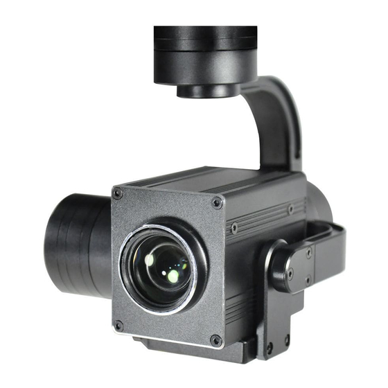
Important Note 1.Product Introduction 1.1 Introduction Z10F is a gimbal camera with 3 axis, 10x optical zoom lens, effective 4 megapixel. It features light and compact, metal housing and anti-interference. The 3 axis gimbal can achieve stabilization in yaw, roll and pitch. The integrated design of damping system and gimbal can greatly reduce mechanical vibration. -
Page 3: Standard Version
1.2 In the Box A. Standard Version Gimbal Camera USB to TTL Cable x 1 pc x 1 pc Copper Cylinder M3 Screw x 4 pcs x 8 pcs Power Cable x 1 pc B. Viewport Version Gimbal Camera USB to TTL Cable x 1 pc x 1 pc Copper Cylinder... -
Page 4: Installation Instruction
TTL / S.BUS Control Cable x 1 pc TTL Connect Cable x 3 pcs 2. Installation Instruction 2.1 Overview [10] [12] [11] Control Box Back Side (Standard Version) [10] [13] [12] Viewport [11] (Viewport Version) - Page 5 [8] Roll axis motor [1] Control box [9] Pitch axis motor [2] Upper damping board [10] 3-6S power interface [3] Lower damping board [11] Micro HDMI interface [4] FHD zoom camera [12] Ethernet interface [5] Damping ball [6] Yaw axis motor [13] Viewport unlock button [7] TF card slot Please ensure that there isn’t any obstacle while the...
- Page 6 2.2.2 Control Box Printing (Viewport Version) Front Side POWER Left Side ETHERNET UART & S.BUS Right Side...
- Page 7 2.3 Device Dimensions (Standard Version) Unit: mm 69.9 60.0 69.8 69.9 75.3 110.3...
- Page 8 2.3 Device Dimensions (Viewport Version) Unit: mm 78.0 Control Box 91.0 91.0 81.5 91.0 75.3 110.3...
- Page 9 2.4 Install Mounting Part (1) Find out the arrow on the gimbal which indicating the yaw heading of the payload (i.e. the lens direction when the camera power on), and synchronize with the direction specified by the UAV. (2) Fix one end of the copper cylinder on the screw hole of lower damping board, and use M3 screw to fasten it.
- Page 10 2.5 Viewport Release Instruction × 1. Make sure the two white stripes indicated in above picture are aligned with each other. (If the stripes are not aligned to each other, please pinch the connector part and turn it to left manually)
- Page 11 2. Align the white dot (unlock icon) to the red triangle (below unlock button), push the gimbal into the Viewport completely and then rotate the gimbal camera anticlockwise. 3. When you hear "click" sound (when red dot is aligned to the red triangle) means the gimbal camera and Viewport has been locked.
-
Page 12: Install Tf Card
2.6 Install TF Card TF (Micro SD card): Install the TF card to the card slot (Re. 2.1 Overview). Support max 32GB. Request Class 10 (10m/s) transmis- sion speed or higher and FAT32 or exFAT format. Make sure device is power off when inserting the TF card, hot plugging is not supported. -
Page 13: Signal Control
3. Signal Control 3.1 PWM Control Control the gimbal camera functions by the multiplex pulse width modulation signal outputted by PWM channel of the remote control receiver. The camera needs up to 6 control channels of PWM (to expand tracking function use up to 7 PWM channels). You can choose needed functions according to actual usage to reduce the required number of PWM channels. - Page 14 Receiver Remote Controller Connection Diagram (Viewport Version) 3.1.2 PWM Control Operation Instruction 1) Pitch (PWM Pitch channel in to control Pitch. Joystick, rotary knob or 3-gear switch on remote control are optional. 3-gear switch as example.) Position 1 Position 2 Position 3 Low Gear Middle Gear...
- Page 15 2) Yaw (PWM Yaw channel in to control Yaw. Joystick, rotary knob or 3-gear switch on remote control are optional. 3-gear switch as example.) Position 1 Position 2 Position 3 Low Gear Middle Gear High Gear Yaw Left Yaw Stop Yaw Right 3) Mode (PWM Mode channel in to adjust speed control/one key to Home position etc functions.
- Page 16 Function of continuous switching: 3.1) Operate 1 time continuously and quickly, from position 2 - 3 - 2, to Home position. 3.2) Operate 2 times continuously and quickly, from position 2 - 3 - 2 - 3 - 2, the camera lens looks vertically down. 3.3) Operate 3 times continuously and quickly, from position 2 - 3 - 2 - 3 - 2 - 3 - 2, to disable Follow Yaw Mode (gimbal yaw not follows by frame)
- Page 17 Position 1 Position 2 Position 3 Low Gear Middle Gear High Gear 6) Pic/Rec (PWM Pic/Rec channel in to control take picture and record. Joystick, rotary knob or 3-gear switch on remote control are optional. 3-gear switch as example.) Position 1 Position 2 Position 3 Low Gear...
- Page 18 7) Multi: PWM channel, no control 3.2 Serial Port / TTL Control TTL communication requirements: TTL signal is 3.3V, baud rate: 115200, data bit 8, stop bit 1, no parity, HEX send and receive. Connection Diagram (PC - USB to TTL Cable- Gimbal Camera as example): Gimbal Camera Cable...
- Page 19 TTL control protocol file. ViewLink is a user interface developed by Viewpro for Viewpro gimbal cameras, you can download it from Viewpro website (www.viewpro- tech.com) or ask distributors for installation package.
-
Page 20: S.bus Control
Connect serial port of gimbal to pins, DO NOT connect with power supply. The default baud rate of serial port is 115200, which can be changed according to the docking equipment. 3.3 S.BUS Control Control the gimbal camera functions by one combining signals. Connect the external S.Bus to S.Bus port on the control box, and the external S.bus signal GND connect to the GND interface of the control box. - Page 21 Receiver Remote Control Wiring Diagram Viewport Version S.Bus control mode: default S.Bus signal channel 9-15 to control gimbal camera functions (the function of channel is consistent with corresponding channel in PWM function description) Channel 9: Yaw Control Channel 10: Pitch Control Channel 11: Mode Control Channel 12: Zoom Control Channel 13: Focus Control...
-
Page 22: Specification
User can set the channels by setting serial command according to the actual requirement. The S.Bus channel position can be arranged in any sequence within channel 1-15 to connect with the flight controller or remote control. 4. Specification General Working voltage Input voltage 3S ~ 6S Output voltage... - Page 23 Gimbal Spec Pitch/Tilt ±90° Roll ±45° Yaw/Pan ±150° Vibration angle Picth/Roll: ±0.02°, Yaw:±0.03° One-key to center √ Camera spec Imager Sensor 1/3inch CMOS Total pixel Effective pixel 2688*1520 Dynamic range 65dB Lens Optical zoom 10x, F=4.9~49mm Min object distance 1.5M Horizontal: 53.2°(Wide end) ~ 5.65°(Tele end) Viewing angle Vertical: 39.8°(wide end) ~ 4.2°(tele end)
- Page 24 AV output Standard CVBS 1Vp-p S/N ratio 38dB Min illumination Color 0.05lux@F1.6 Backlight Backlight compensation/strong light inhibition compensation Gain Auto White balance Auto/Manual Shutter speed Auto Control system UART/IR/PWM Communication PELCO-D, Hitachi protocol or VISCA protocol Focus Auto/Manual/One-time automatic focus Focus speed Lens initialization Built-in...
- Page 25 TF card. 3. Does Z10F support taking photos during recording? A: No, not support. Z10F has photo mode and record mode. You need to switch to photo mode to take picture. 4. What is the focusing mode of Z10F?
Need help?
Do you have a question about the Z10F and is the answer not in the manual?
Questions and answers