
Related Manuals for Viewpro Z-6KA7


Summary of Contents for Viewpro Z-6KA7
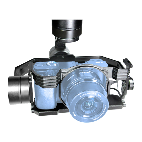
- Page 1 Z-6KA7 SONY A6000 Series Gimbal User Manual User Manual Standard Version Viewport Version 标准版 快拆版 For more details please scan the QR code or visit our website: www.viewprotech.com...
-
Page 2: Disclaimer And Warning
Viewpro product. Disassemble the gimbal camera by user is not permitted, as which may cause the camera does not work normally. Viewpro accepts no liability for damage, injury or any legal responsi- bility incurred directly or indirectly from the use of this project. The user shall observe safe and lawful practices including, but no limited to, those set forth in the manual. -
Page 3: Standard Version
1.2 In the Box A. Standard Version Gimbal Camera USB to TTL Cable x 1 pc x 1 pc Copper Cylinder M3 Screw x 4 pcs x 8 pcs Power Cable x 1 pc Thumb screw x 1 pc B. Viewport Version Gimbal Camera USB to TTL Cable x 1 pc... -
Page 4: Installation Instruction
TTL / S.BUS Control Cable x 1 pc TTL Connect Cable x 3 pcs Thumb screw x 1 pc 2. Installation Instruction 2.1 Overview Control Box Back Side (Standard Version) [10] Viewport (Viewport Version) - Page 5 [6] Roll axis motor [1] Control box [7] Pitch axis motor [2] Upper damping board [8] 3-6S power interface [3] Lower damping board [9] HDMI interface [4] Damping ball [10] Viewport unlock button [5] Yaw axis motor Please ensure that there isn’t any obstacle while the motor rotating.
- Page 6 2.2.2 Control Box Printing (Viewport Version) Front Side POWER Left Side ETHERNET UART & S.BUS Right Side...
- Page 7 2.3 Device Dimensions (Standard Version) Unit: mm 62.2 107.0 107.0 159.2 202.8...
- Page 8 2.3 Device Dimensions (Viewport Version) Unit: mm Control Box 202.8 159.2...
- Page 9 2.4 Install Mounting Part (1) Find out the arrow on the gimbal which indicating the yaw heading of the payload (i.e. the lens direction when the camera power on), and synchronize with the direction specified by the UAV. (2) Fix one end of the copper cylinder on the screw hole of lower damping board, and use M3 screw to fasten it.
- Page 10 2.5 Viewport Release Instruction × 1. Make sure the two white stripes indicated in above picture are aligned with each other. (If the stripes are not aligned to each other, please pinch the connector part and turn it to left manually)
- Page 11 2. Align the white dot (unlock icon) to the red triangle (below unlock button), push the gimbal into the Viewport completely and then rotate the gimbal camera anticlockwise. 3. When you hear "click" sound (when red dot is aligned to the red triangle) means the gimbal camera and Viewport has been locked.
-
Page 12: Signal Control
2.6 Image Output Interface HDMI: micro HDMI interface, HD output 1080P; AV: no AV output 3. Signal Control 3.1 PWM Control Control the gimbal camera functions by the multiplex pulse width modulation signal outputted by PWM channel of the remote control receiver. - Page 13 Receiver Remote Controller Connection Diagram (Viewport Version) 3.1.2 PWM Control Operation Instruction 1) Pitch (PWM Pitch channel in to control Pitch. Joystick, rotary knob or 3-gear switch on remote control are optional. 3-gear switch as example.) Position 1 Position 2 Position 3 Low Gear Middle Gear...
- Page 14 2) Yaw (PWM Yaw channel in to control Yaw. Joystick, rotary knob or 3-gear switch on remote control are optional. 3-gear switch as example.) Position 1 Position 2 Position 3 Low Gear Middle Gear High Gear Yaw Left Yaw Stop Yaw Right 3) Mode (PWM Mode channel in to adjust speed control/one key to Home position etc functions.
- Page 15 3.1) Operate 1 time continuously and quickly, from position 2 - 3 - 2, to Home position. 3.2) Operate 2 times continuously and quickly, from position 2 - 3 - 2 - 3 - 2, the camera lens looks vertically down. 3.3) Operate 3 times continuously and quickly, from position 2 - 3 - 2 - 3 - 2 - 3 - 2, to disable Follow Yaw Mode (gimbal yaw not follows by frame)
- Page 16 Switch from Position 2 to 1: Focus Tele. Switch from Position 2 to 3: Focus Near. 6) Pic/Rec (PWM Pic/Rec channel in to control take picture and record. Joystick, rotary knob or 3-gear switch on remote control are optional. 3-gear switch as example.) Position 1 Position 2 Position 3...
- Page 17 3.2 Serial Port / TTL Control TTL communication requirements: TTL signal is 3.3V, baud rate: 115200, data bit 8, stop bit 1, no parity, HEX send and receive. Connection Diagram (PC - USB to TTL Cable- Gimbal Camera as example): Gimbal Camera Cable RX (White)
-
Page 18: S.bus Control
TTL control protocol file. ViewLink is a user interface developed by Viewpro for Viewpro gimbal cameras, you can download it from Viewpro website (www.viewpro- tech.com) or ask distributors for installation package. - Page 19 5V OUTPUT Remote Control Receiver Wiring Diagram Standard Version Receiver Remote Control Wiring Diagram Viewport Version...
- Page 20 S.Bus control mode: default S.Bus signal channel 9-15 to control gimbal camera functions (the function of channel is consistent with corresponding channel in PWM function description) Channel 9: Yaw Control Channel 10: Pitch Control Channel 11: Mode Control Channel 12: Zoom Control Channel 13: Focus Control Channel 14: Pic/Rec Control Channel 15: Multi Backup...
-
Page 21: Specification
4. Specification Hardware Parameter Working voltage Input voltage 3S ~ 6S Dynamic current 100~300mA @ 12V (Only gimbal) Idle current 100mA @ 12V (Only gimbal) Working environment -20℃ ~ +60℃ temp Output micro HDMI / AV Control method PWM / TTL / S.BUS Gimbal Spec Pitch/Tilt: ±160°, Roll: ±50°, Yaw/Pan: ±300°... - Page 22 Object Tracking (Optional) Update rate of 50Hz deviation pixel Output delay of deviation pixel Minimum object contrast Minimum object size 32*32 pixel Maximum object size 128*128 pixel Tracking speed 32 pixel/frame Object memory time 100 frames (4s) The mean square root values of pulse <...
- Page 23 A: The USB connector of the gimbal is poor contacted with the USB holder of the camera, plug it again. 1. Z-6KA7 gimbal HDMI imgae cannot be outputted? A: The HDMI cable is directly connected to the CAMERA'S HDMI port and monitor, excluding possible issue of cable quality or...
Need help?
Do you have a question about the Z-6KA7 and is the answer not in the manual?
Questions and answers