Viewpro Z40K User Manual
40x 4k video uhd gimbal camera
Hide thumbs
Also See for Z40K:
- User manual (14 pages) ,
- Quick start manual (11 pages) ,
- User manual (14 pages)

Subscribe to Our Youtube Channel
Related Manuals for Viewpro Z40K


Summary of Contents for Viewpro Z40K
- Page 1 Z40K 40x 4K video UHD Gimbal Camera User Manual Standard Version Viewport Version 标准版 快拆版 For more details please scan the QR code or visit our website: www.viewprotech.com...
-
Page 2: Disclaimer And Warning
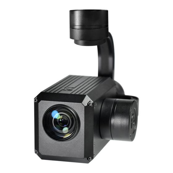
Important Note 1.Product Introduction 1.1 Introduction Z40K is a 25.9MP 4K camera with 3-axis gimbal. It's powered by Panasonic 1/2.3” COMS module, has up to 40x mixed zoom. With advanced OIS function, Z40K can compensate the subtle movements of the UAV to keep the camera stable even with 20 times optical zoom. -
Page 3: Standard Version
1.2 In the Box A. Standard Version Gimbal Camera USB to TTL Cable x 1 pc x 1 pc Copper Cylinder M3 Screw x 4 pcs x 8 pcs Power Cable x 1 pc B. Viewport Version Gimbal Camera USB to TTL Cable x 1 pc x 1 pc Copper Cylinder... -
Page 4: Installation Instruction
TTL / S.BUS Control Cable x 1 pc TTL Connect Cable x 3 pcs Ethernet Cable x 1 pc 2. Installation Instruction 2.1 Overview [11] [13] [12] Control Box Back Side (Standard Version) [11] [14] [13] Viewport [12] (Viewport Version) - Page 5 [9] Roll axis motor [1] Control box [10] Pitch axis motor [2] Upper damping board [11] 3-6S power interface [3] Lower damping board [12] Micro HDMI interface [4] FHD zoom camera [13] Ethernet interface [6] Damping ball [14] Viewport unlock button [7] Yaw axis motor [8] TF card slot Please ensure that there isn’t any obstacle while the...
- Page 6 2.2.2 Control Box Printing (Viewport Version) Front Side POWER Left Side ETHERNET UART & S.BUS Right Side...
- Page 7 2.3 Device Dimensions (Standard Version) Unit: mm 69.9 60.0 69.7 57.2 95.3 69.9 33.0 13.5 153.0...
- Page 8 2.3 Device Dimensions (Viewport Version) Unit: mm Control Box 90.9 78.0 81.6 91.0 81.5 25.5 13.0 57.2 153.0 95.3...
- Page 9 2.4 Install Mounting Part (1) Find out the arrow on the gimbal which indicating the yaw heading of the payload (i.e. the lens direction when the camera power on), and synchronize with the direction specified by the UAV. (2) Fix one end of the copper cylinder on the screw hole of lower damping board, and use M3 screw to fasten it.
- Page 10 2.5 Viewport Release Instruction × 1. Make sure the two white stripes indicated in above picture are aligned with each other. (If the stripes are not aligned to each other, please pinch the connector part and turn it to left manually)
- Page 11 2. Align the white dot (unlock icon) to the red triangle (below unlock button), push the gimbal into the Viewport completely and then rotate the gimbal camera anticlockwise. 3. When you hear "click" sound (when red dot is aligned to the red triangle) means the gimbal camera and Viewport has been locked.
-
Page 12: Install Tf Card
2.6 Install TF Card TF (Micro SD card): Install the TF card to the card slot (Re. 2.1 Overview). Support max 128GB. Request Class 10 (10m/s) transmis- sion speed or higher and FAT32 or exFAT format. Make sure device is power off when inserting the TF card, hot plugging is not supported. -
Page 13: Signal Control
When using user interface software Viewlink for network connection, the network of external device (computer) should be the IP address: 192.168.1.2 (choose the last byte among 2~254, can not be 100 same as the gimbal), subnet mask: 255.255.255.0, Default gateway: 192.168.2.1, and all firewalls of the computer must be closed. - Page 14 PWM IN 5V OUTPUT Remote Controller Receiver Connection Diagram (Standard Version) Receiver Remote Controller Connection Diagram (Viewport Version)
- Page 15 3.1.2 PWM Control Operation Instruction 1) Pitch (PWM Pitch channel in to control Pitch. Joystick, rotary knob or 3-gear switch on remote control are optional. 3-gear switch as example.) Position 1 Position 2 Position 3 Low Gear Middle Gear High Gear Pitch Up Pitch Stop Pitch Down...
- Page 16 Position 1 Position 2 Position 3 Low Gear Middle Gear High Gear Position 1: Low speed mode, control pitch / yaw with this mode at lowest speed Position 2: Middle speed mode, control pitch / yaw with this mode at middle speed Position 3: High speed mode, control pitch / yaw with this mode at highest speed...
- Page 17 4) Zoom (PWM Zoom channel in to control Zoom. Joystick, rotary knob or 3-gear switch on remote control are optional. 3-gear switch as example.) Position 1 Position 2 Position 3 Low Gear Middle Gear High Gear Zoom Out Stop Zoom Zoom In 5) Focus (not functional for this channel).
- Page 18 7) Multi: Backup channel Position 1 Position 2 Position 3 Middle Gear High Gear Low Gear 3.2 Serial Port / TTL Control TTL communication requirements: TTL signal is 3.3V, baud rate: 115200, data bit 8, stop bit 1, no parity, HEX send and receive. Connection Diagram (PC - USB to TTL Cable- Gimbal Camera as example): Gimbal Camera...
- Page 19 TTL control protocol file. ViewLink is a user interface developed by Viewpro for Viewpro gimbal cameras, you can download it from Viewpro website (www.viewpro- tech.com) or ask distributors for installation package.
- Page 20 Connect serial port of gimbal to pins, DO NOT connect with power supply. The default baud rate of serial port is 115200, which can be changed according to the docking equipment. 3.3 S.BUS Control Control the gimbal camera functions by one combining signals. Connect the external S.Bus to S.Bus port on the control box, and the external S.bus signal GND connect to the GND interface of the control box.
- Page 21 Receiver Remote Control Wiring Diagram Viewport Version S.Bus control mode: default S.Bus signal channel 9-15 to control gimbal camera functions (the function of channel is consistent with corresponding channel in PWM function description) Channel 9: Yaw Control Channel 10: Pitch Control Channel 11: Mode Control Channel 12: Zoom Control Channel 13: Focus Control...
-
Page 22: Specification
User can set the channels by setting serial command according to the actual requirement. The S.Bus channel position can be arranged in any sequence within channel 1-15 to connect with the flight controller or remote control. TTL control and S.bus control cannot coexist at the same time for standard version. - Page 23 micro HDMI( HD output 1080P 50/60fps ) / Output IP (720P / 1080P 25 / 30fps) SD card (Up to 128G, class 10, FAT32 or Local-storage ex FAT format) Control method PWM / TTL / SBUS Gimbal Spec Pitch/Tilt: -120°~120°, Roll: ±70°, Yaw/Pan: ±300°...
- Page 24 Optical Image 5 axis Optical Image Stabilization Stabilization Video storage format MPEG-4 (4k:3840*2160 25/30fps FHD:1080P 50/60fps) Record shutter speed 1/30 ~ 1/8000 (Manual) Photo storage format JPG(4K:20.4M FHD:14M) Picture shutter speed 1/2 ~ 1/2000 (Manual) Dynamic range 65dB Min object distance 1.5M Horizontal: 62.95°(Wide end) ~ 3.45°(Tele Viewing angle...
- Page 25 Control system UART / IR / PWM Communication 1080P 30fps local TF card protocol Focus Auto / Manual / One-time automatic focus Focus speed Focus Auto / Manual / One-time automatic focus Lens initialization Built-in User presetting bit 20 sets Image rotation 180°, Horizontal/Vertical mirror image Facial recognition...
- Page 26 1. Does Z40K support taking photos during recording? A: Yes 2. How to set the storage format of Z40K? A: When video format is set to 1080p mode , the storage resolution is 1920*1080, 50fps or 60 fps for optional; When video format is set to 4K mode, the storage resolution is 3840*2160, 25fps or 30 fps for optional.
Need help?
Do you have a question about the Z40K and is the answer not in the manual?
Questions and answers