Table of Contents
Advertisement
Advertisement
Table of Contents

Related Manuals for Breas Clearway 2


Summary of Contents for Breas Clearway 2
- Page 1 Service Manual Technical Instructions for Use 2210.2657 Revision 3.0...
-
Page 2: Table Of Contents
Table of Contents Introduction ......................4 Manufacturer Contact Information ..............4 What is the Clearway 2? .................. 4 Intended Use ....................4 Service Personnel Training Requirements ............5 About this Manual .................... 5 Icons ........................ 6 Maintenance Instructions ..................7 Purpose ...................... - Page 3 Alarm Battery ....................45 Technical Troubleshooting ................... 46 Suggested Acceptance Test ................. 48 Appendices ......................49 Emissions and Immunity Declaration ............. 49 Returning Products to Breas ................49 Patient Settings Record ................. 50 Inspection record template ................51 Optional Accessories ..................53 Introduction NIPPY Clearway 2 Service Manual 2210.2657 Rev 3.0...
-
Page 4: Introduction
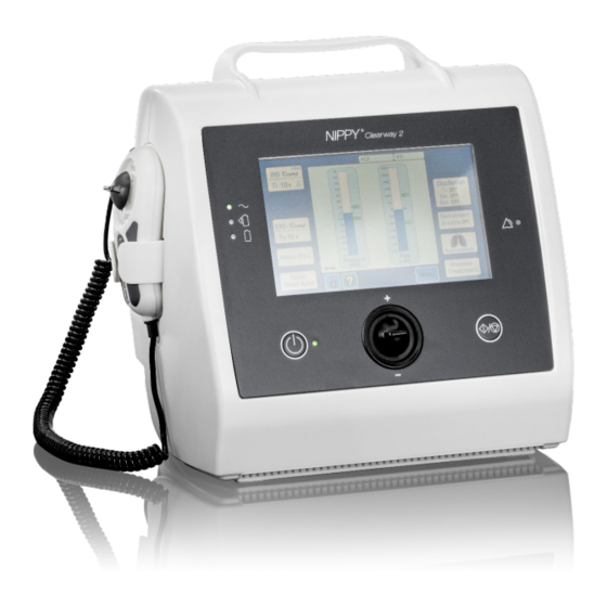
1 Introduction This Chapter gives an overview of the Clearway 2 airway clearance device and this service manual. Manufacturer Contact Information To Contact Breas Medical Ltd: Unit A2, Timothy’s Bridge Road Tel: +44 (0)1789 293460 Stratford-upon-Avon email: uk@breas.com Warwickshire, United Kingdom CV37 9HW www.breas.com... -
Page 5: Service Personnel Training Requirements
Service personnel wishing to undertake service or repair of the Clearway 2 shall first undertake a technical training course provided by Breas Medical Ltd. Please contact Breas Medical Ltd if training is required or if you... -
Page 6: Icons
Risk of equipment damage, loss of data, extra work, or unexpected results Note Information that may be valuable but is not critically important Reference Reference to other manuals with additional information on a specific topic Introduction NIPPY Clearway 2 Service Manual 2210.2657 Rev 3.0... -
Page 7: Maintenance Instructions
Deviation from these instructions may lead to risk of personal injury Purpose Carrying out regular inspection and preventative maintenance at the intervals specified in this manual will ensure that the Clearway 2 will continue to perform to specification during its service lifetime. Introduction... -
Page 8: Service Schedule
WARNING! Safety Precautions • Follow the safety precautions when working on the Clearway 2 • Do not work on the Clearway 2 with the case open and the power supply connected, unless instructed to do so in this manual • Always use extreme caution when working on the Clearway 2 when connected to any power source with the case open •... -
Page 9: Inspection Equipment And Tools
• Pozidrive screwdriver No. 1 • Hex screwdriver 2mm • Hex screwdriver 2.5mm (To open the battery cover) • Soldering iron, to remove and replace the alarm battery every 5 years Maintenance Instructions NIPPY Clearway 2 Service Manual 2210.2657 Rev 3.0... -
Page 10: Replacement Parts
Record / save the patient settings as required Determine the level of service required Labels and markings Labels and markings should be attached and fully legible: Front panel markings. Information label on rear panel Maintenance Instructions NIPPY Clearway 2 Service Manual 2210.2657 Rev 3.0... -
Page 11: External Inspection
Inspect the condition of the side sockets and cover (USB, SD card slot and SpO2 sensor socket). Power Connection Inspect the AC Mains cable and the Clearway 2 AC inlet socket. Accessories Inspect any accessories returned with the Clearway 2. -
Page 12: Function Test
Accessories made available at time of testing shall also be function checked. Pressure and Flow Test Connect the Clearway 2 patient outlet to a manometer or gas flow analyser via a breathing circuit (part 2210.101) and connect a test lung (part 6011) to the measurement devices outlet. - Page 13 Select Manual Mode and ensure that the remote hand control switch activates insufflation and exsufflation appropriately. The Start/Stop button must start or stop a treatment in the Auto Modes only. Maintenance Instructions NIPPY Clearway 2 Service Manual 2210.2657 Rev 3.0...
- Page 14 Connect the SpO cable and sensor accessory to the SpO socket on the side of the Clearway 2, A message will appear indicating that the sensor is connected. Verify that a “?” symbol is displayed next to SpO when no signal is present.
-
Page 15: Internal Inspection
Open the case as described in this manual. Internal clean Clean out any dust which may have accumulated inside the Clearway 2. Inspect electrical connections Visually inspect all internal electrical cables. Cable sheathing must be intact and in good condition and ensure cables have not been damaged. -
Page 16: Electrical Safety
Every 5 years remove the valve assembly and clean as described in chapter 7 of this manual. Electrical Safety Clearway 2 is a Class II, type BF medical electrical device. Electrical equipment with dual isolation and body floating (isolated) applied parts according to IEC 60601-1. -
Page 17: Service Menu
Preferences. Service screens are in English language only. Unlocking the Clearway 2 Unlock by holding the padlock icon until a pop up appears and acknowledge it. Clearway 2 must always be unlocked before accessing the service menu. To Enter the Service Mode: Press the menu button and select service menu, input the code 4321 and press the tick button. -
Page 18: Calibration
Press ‘Next’ to move to the next window. (To exit at anytime press the Blue square with arrows pointing inwards.) 2. Zero the transducer values, by pressing the ‘ZERO’ buttons (in any order), then press ‘Next’ Service Menu NIPPY Clearway 2 Service Manual 2210.2657 Rev 3.0... - Page 19 Then press ‘Next’. NOTE: The blower will default to creating a pressure of around 45 O, we recommended to calibrate this point. It is only required to calibrate this one point. Service Menu NIPPY Clearway 2 Service Manual 2210.2657 Rev 3.0...
- Page 20 NOTE: With the 6mm leak, the blower will default to a flow of around -160 L/m, we recommend to calibrate this point. It is only required to calibrate this one point. Service Menu NIPPY Clearway 2 Service Manual 2210.2657 Rev 3.0...
- Page 21 PCB has been replaced or a software upgrade has been performed. 1. Enter the service menu and select ‘valve calibration’. 2. Do not connect anything to the patient outlet. Press ‘ZERO’ then ‘Next’. Service Menu NIPPY Clearway 2 Service Manual 2210.2657 Rev 3.0...
- Page 22 When this achieved the valve spool will move to between the two end positions to set them. The whole process takes around 2 minutes. 4. When complete a message will be displayed. Service Menu NIPPY Clearway 2 Service Manual 2210.2657 Rev 3.0...
-
Page 23: Diagnostic Screen
The treatment settings may be restored to the defaults, e.g. if a device is to be used on a different patient or stored in an equipment library. (This is the same as the Reset Settings button in the main menu) Service Menu NIPPY Clearway 2 Service Manual 2210.2657 Rev 3.0... -
Page 24: Part Identification
4 Part identification Inside Front Case Part identification NIPPY Clearway 2 Service Manual 2210.2657 Rev 3.0... -
Page 25: Display Pcb
Display PCB Part identification NIPPY Clearway 2 Service Manual 2210.2657 Rev 3.0... -
Page 26: Inside Rear Case
Inside Rear Case Part identification NIPPY Clearway 2 Service Manual 2210.2657 Rev 3.0... -
Page 27: Power Pcb
Power PCB Part identification NIPPY Clearway 2 Service Manual 2210.2657 Rev 3.0... -
Page 28: Parts List
Air Path Silicone CV to Blower B 2210.2298 Air Path Silicone Valve to Flow Sensor 2210.2653 Air Path Silicone Flow Sensor to Enclosure 2210.2654 Silicone Pressure Sensor Tube 100mm 2210.2822 Pressure Pick Up 2210.2718 Parts List NIPPY Clearway 2 Service Manual 2210.2657 Rev 3.0... -
Page 29: Functional Diagrams
6 Functional Diagrams Clearway 2 block diagram Functional Diagrams NIPPY Clearway 2 Service Manual 2210.2657 Rev 3.0... -
Page 30: Control Pcb Block Diagram
Control PCB block diagram Functional Diagrams NIPPY Clearway 2 Service Manual 2210.2657 Rev 3.0... -
Page 31: Display Pcb Block Diagram
Display PCB block diagram Functional Diagrams NIPPY Clearway 2 Service Manual 2210.2657 Rev 3.0... -
Page 32: Pneumatic Diagrams
Pneumatic diagrams Functional Diagrams NIPPY Clearway 2 Service Manual 2210.2657 Rev 3.0... -
Page 33: Removing Main Components
Observe ESD handling precautions Removing and Replacing the Internal Battery Switch off the Clearway 2 and disconnect the AC mains supply. To remove the battery, unscrew the 3 fixing screws on the battery door at the rear of the device as shown in the diagram below. Slide the door outwards to reveal the internal battery. -
Page 34: Opening And Closing The Case
To open the case, loosen and remove the 8 case fixing screws at the rear of the device using a T15 x 200mm screwdriver. With the Clearway 2 in its normal upright position carefully pull the front and rear case halves apart. There are two cables connecting the control PCB in the rear to the Display PCB on the front, these must now be disconnected. -
Page 35: Removing And Replacing The Power Control Pcb
Removing and Replacing the Power Control PCB Switch off the Clearway 2 and disconnect the AC mains supply. Follow the instructions on how to open the case. Disconnect Internal and/or External batteries first To remove the Power/Control PCB, disconnect all electrical connections from the Power/Control PCB. -
Page 36: Removing And Replacing The Display Command Pcb
NOTE: Removing the valve assembly makes access to the blower jacket easier. To remove the Blower, place the Clearway 2 on is back. Disconnect the blower electrical connector PL1. Open the silicone blower ‘jacket’ by releasing the securing strap from the left- hand side and pulling out the two lugs on the right-hand side. -
Page 37: Removing And Replacing The Valve Assembly
Switch off the Clearway 2 and disconnect the AC mains supply. Follow the instructions on how to open the case. To remove the valve assembly, Place the Clearway 2 on its back. First disconnect the electrical connection from the Flow transducer, then remove the flow transducer silicone pipe from the valve outlet. -
Page 38: Removing And Replacing The Power Supply
Valve control connector CON 6, valve drive connector CON 5. Removing and Replacing the Power Supply Switch off the Clearway 2 and disconnect the AC mains supply. Follow the instructions on how to open the case. Place the Clearway 2 on its back. -
Page 39: Removing And Replacing The Clock Battery
We recommend that clock battery is replaced every 5 years. The specified part in this manual must be used. Switch off the Clearway 2 and disconnect the AC mains supply. Follow the instructions on how to open the case The clock battery is located in the holder (BAT 2) on the display PCB. -
Page 40: Removing And Replacing The Alarm Battery
We recommend the Alarm battery is replaced every 5 years. The specified part in this manual must be used. Switch off the Clearway 2 and disconnect the AC mains supply. Follow the instructions on how to open the case. Before removing the battery. Set the SW3 DIP switches 1 (A_BAT) = OFF and 2 (A_DIS) = ON Remove the display command PCB. - Page 41 When the battery has been replaced, reset the SW3 DIP switches to the original positions: 1 (A_ BAT) = ON and 2 (A_DIS) = Check the date and time and adjust after changing the alarm battery. Removing Main Components NIPPY Clearway 2 Service Manual 2210.2657 Rev 3.0...
-
Page 42: Electronics
Power Control board, mounted in the base of the rear case. There are five microprocessors in the Clearway 2. The main and valve micro- controllers and the alarm micro communicate with the display microprocessor to control and monitor all of the device functions. -
Page 43: Display Command Pcb
• Real Time Clock • Alarm Battery • Clock Battery • Speakers Regulators 3.3 V Communication (comms) PCB • Comms Processor • SD Card Interface • USB interface • SpO2 interface Electronics NIPPY Clearway 2 Service Manual 2210.2657 Rev 3.0... -
Page 44: Pneumatic System
A flow transducer is fitted at the valve outlet, it is used for Cough Peak Flow measurements, estimated volume measurements and flow control in IPPB mode. Pneumatic System NIPPY Clearway 2 Service Manual 2210.2657 Rev 3.0... -
Page 45: Batteries
An internal battery takes around 2.5 hours to fully charge. Clock Battery The Clearway 2 uses a 3V Lithium coin cell to supply power to the internal clock. We recommend this battery is replaced every 5 years. The specified part in this manual must be used. -
Page 46: Technical Troubleshooting
Faulty Power PCB Replace power PCB. Manual switch not Front / remote switch Check function with working. fault. front and remote switch. Display PCB fault. Check switch connection CON 2. Replace switch Technical Troubleshooting NIPPY Clearway 2 Service Manual 2210.2657 Rev 3.0... - Page 47 Display PCB fault Replace Display PCB. Sensor not Sensor fault. Try another sensor. recognised Link cable fault. Try another cable. Comms PCB fault. Replace Comms PCB Power PCB fault. Replace Power PCB. Technical Troubleshooting NIPPY Clearway 2 Service Manual 2210.2657 Rev 3.0...
-
Page 48: Suggested Acceptance Test
Measured plateau pressures shall be within ±3.5 cmH of set point. • Batteries If the Clearway 2 has a battery fitted ensure that the battery icon is displayed and the Clearway 2 switches to battery power when the AC mains is disconnected. -
Page 49: Appendices
13 Appendices Emissions and Immunity Declaration The Clearway 2 is tested for electromagnetic emission and immunity according to IEC 60601-1-2-4 edition. See the Clinicians Instructions For Use manual for declarations and information about performed tests. Returning Products to Breas Use the RMA (Return Material Authorisation) if you want to return any product to Breas. -
Page 50: Patient Settings Record
Patient Settings Record This page can be copied and used for noting the patient’s settings. Patient Settings – Breas NIPPY Clearway 2 Patient ………………………………………………………………… Date ………………………………………………………………… Clinic ………………………………………………………………… Set by ………………………………………………………………… Patient Circuit ………………………………………………………… Mode ………………………………………………………………… INS Pressure ………… Ins Trig ………….…… EXS Pressure……………... -
Page 51: Inspection Record Template
Labels and Markings Visual Inspection Filter Change Insufflation Pressure Exsufflation Pressure Flow Front Switch Internal Battery (if used) External Battery (if used) SpO2 sensor (if used) Mains Fail Electrical Safety test 2.10 Appendices NIPPY Clearway 2 Service Manual 2210.2657 Rev 3.0... - Page 52 Every 5 years Procedure Section PASS / FAIL /Comments Internal Clean Electrical Connections Mechanical Fastenings Clean Valve Replace clock battery 7.10 Replace alarm battery 7.11 Notes NIPPY Clearway 2 Service Manual 2210.2657 Rev 3.0...
-
Page 53: Optional Accessories
Senor Adult 006589 Senor Paediatric 006590 Memory Card 006705 Internal Battery 2210.3002 Use with other manufacturer’s accessories or non-approved Breas accessories supplied or recommended by Breas may cause the device to malfunction. NIPPY Clearway 2 Service Manual 2210.2657 Rev 3.0... - Page 54 ENGLISH – EU Breas Medical AB Företagsvägen 1 SE-435 33, Mölnlycke Sweden Breas Medical AB · UNIT A2, The Bridge Business Centre, Timothy’s Bridge Road Stratford-upon-Avon, England, CV37 9HW Phone + 44 (0) 1789 293 460 www.breas.com uk@breas.com · Company registered in England and Wales no. 07190611...
Need help?
Do you have a question about the Clearway 2 and is the answer not in the manual?
Questions and answers
The screen keeps freezing and we can’t turn it off to re start it
If the Breas Clearway 2 screen keeps freezing and cannot be turned off to restart, press and hold the standby button continuously for twenty seconds to shut down the device.
This answer is automatically generated