Table of Contents
Advertisement
DOC 0917
INSTRUCTION MANUAL
FOR THE NIPPY ST+
POSITIVE PRESSURE
Version 6 November 2017
VENTILATOR
This book must be kept with the machine
Breas Medical Ltd
Unit A2, The Bridge Business Centre
Timothy's Bridge Road
Stratford Enterprise Park
Stratford–upon-Avon,
Warwickshire. CV37 9HW
Tel: 01789 293460
www.nippyventilator.com
Advertisement
Table of Contents

Related Manuals for Breas NIPPY ST+


Summary of Contents for Breas NIPPY ST+
- Page 1 DOC 0917 INSTRUCTION MANUAL FOR THE NIPPY ST+ POSITIVE PRESSURE VENTILATOR This book must be kept with the machine Breas Medical Ltd Unit A2, The Bridge Business Centre Timothy’s Bridge Road Stratford Enterprise Park Stratford–upon-Avon, Warwickshire. CV37 9HW Tel: 01789 293460 www.nippyventilator.com...
- Page 3 NIPPY ST+ INSTRUCTION MANUAL INDEX Page Introduction Description Intended Use Contraindications Features Explanation of Controls Fascia Buttons Fascia Display Outlets Rear Panel Layout Explanation of Symbols Used Getting Started The Main Screen How to Adjust the NIPPY ST+ The Menu Window How to use the on-screen Menu Structure of the Main Menu How to use the on-screen help...
- Page 4 Factory Service / Repair EMC Declaration and guidelines 35-37 Battery Run Time Test Record Locking the Settings Please note Breas Medical previously traded as B & D Electromedical & some photographs in these instructions still show the name B & D Electromedical.
-
Page 5: Introduction
• In accordance with the operating conditions specified in this operating manual. • In original and unmodified shape and only with accessories specified or approved by Breas Medical Ltd. Every other use may lead to risk of personal injury! CAUTION! -
Page 6: Description
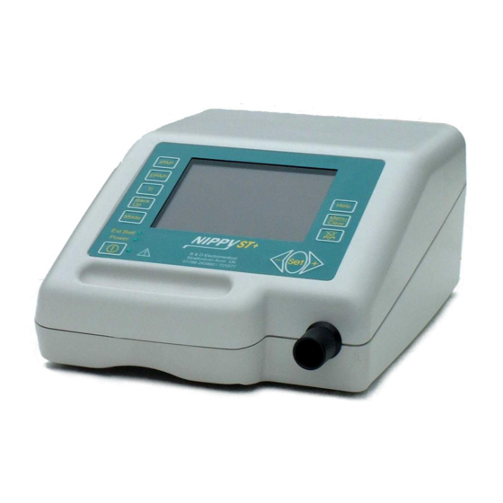
Description The NIPPY ST+ is a pressure controlled, bi-level ventilator. It compresses ambient air and delivers it to the patient through a close fitting nasal mask. The output pressure, can be adjusted by controls on the fascia panel. The Pressure, and all settings are displayed on a colour LCD (Liquid Crystal Display) screen. - Page 7 Alarms Power Fail If the electrical power to the ventilator is interrupted, an audible alarm will sound. This alarm will run for 5 minutes unless cancelled with the mute button. Once cancelled the power fail alarm will not re-activate. Low Internal Battery When running on its optional internal battery, the alarm will operate when the battery is almost depleted The user cannot replace this battery.
- Page 8 Estimated Tidal Volume The estimated tidal volume is a calculated value, based on time and calibrated flow values. The constant leak through the breathing circuit exhalation port is subtracted from this calculation to give a reasonably accurate estimation of tidal volume. The estimated tidal volume is displayed above the bargraph display.
-
Page 9: Intended Use
Intended Use The NIPPY ST+ is intended to provide non-invasive ventilation for non-dependent, spontaneously breathing adult patients with respiratory insufficiency, or respiratory failure. The NIPPY ST+ is not intended for life support or life-sustaining applications or for transport of critical care patients. The NIPPY ST+ is intended for use in clinical settings (e.g., hospitals and sub-acute care institutions) and home environments. -
Page 10: Contraindications
Contraindications The NIPPY ST+ is not a life support ventilator. The use of the device may be contraindicated in patients with the following: • Pneumothorax or pneumomediastinum • Low blood pressure • Cerebrospinal fluid leak, recent cranial surgery or trauma, or raised Intercranial pressure •... -
Page 11: Features
Features Comprehensive alarms with mute facility User friendly intuitive user interface Easily understood alarm messages displayed onscreen 2 modes of ventilation Universal mains input, operates anywhere in the world without transformers Optional internal battery Adjustable flow triggers with trigger indicators Large, colour LCD display, clearly shows all settings 28 days stored, On-screen compliance data Comprehensive event log stores all adjustments, settings, alarm events... -
Page 12: Explanation Of Controls Fascia Buttons
Explanation of controls C le a r Fascia Buttons IPAP - Selects the Inspiratory Positive Airway Pressure adjustment (scaled in cm H 2 O). Value is displayed on screen adjacent to the switch. EPAP - Selects the Expiratory Positive Airway Pressure adjustment (scaled in cm H 2 O). -
Page 13: Fascia Display
Fascia Display 1. Mode Displays current mode of ventilation. 2. Pressure Display - Indicates airway pressure (scaled in cm H Changes colour to red in under / over pressure alarm condition. 3. Rate Display - Indicates patient breath rate (scaled in Breaths Per Minute). -
Page 14: Outlets
Ventilator Outlets 1. Outlet Main Air Outlet to breathing circuit Rear Panel Layout Aux. Power 24 Volt connection for external battery. Connect only recommended battery, part no 0910. RS232 Port For connection to remote alarm or personal computer. Isolated to 1500 Volts. Power Inlet Input mains power connector. -
Page 15: Explanation Of Symbols Used
Explanation of Symbols used on NIPPY ST+ and Accessories Type B Applied parts to EN 60601-1 Alternating Current Direct Current Time Delay Fuse Serial Number Date of Manufacture Attention. Consult Accompanying Documents Switch ON /OFF +► Increase Button ◄- Decrease Button Locked / Unlocked, Purple = total lock, Black = settings locked Alarm Muted Battery charged... -
Page 16: How To Adjust The Nippy St
Getting Started To Switch On Place the NIPPY ST+ on a clean, smooth, hard surface. (NOT carpet) Connect the power lead to the mains power connector on the rear panel. Plug into the mains power supply. Press the Start/Stop button. To Switch Off Press the Start/Stop button. -
Page 17: The Menu Window
The Menu Window The Main Menu gives access to further adjustments and allows you to view information relating to the ventilator usage. How to use the on-screen menu Press the MENU button. The menu window will be displayed in front of the main screen. -
Page 18: Structure Of The Main Menu
Structure of the Main Menu . Adjust Trigger I Trig View / Adjust E Trig View / Adjust 2. User Preferences User Preferences Alarm Volume View / Adjust Display Brightness View / Adjust Display Contrast View / Adjust Display Dimming View / Adjust (Sets time in minutes until display dims, to night time level) Disconnection Alarm... -
Page 19: How To Use The On-Screen Help
How to use the On-screen Help Press the HELP button at any time for a list of help topics. Follow the simple on- screen instructions. Press HELP again to exit. If during setting up, you require a description of a particular parameter, select it then press HELP. - Page 20 Breathing Circuits Breathing circuits to be assembled in the order A-B-C-D from the ventilator end. The NIPPY ST+ uses a single limb circuit. Always use a ventilated mask. Part Number 0792 Breathing circuit volume = 570 ml including filter.
- Page 21 Setting up the NIPPY ST+ in CPAP mode 1. Place the NIPPY ST+ on a clean, level surface. 2. Connect the breathing circuit tube to the outlet. It is recommended that a bacterial filter be fitted between the outlet and the 22mm diameter breathing tube. 3.
-
Page 22: Setting Up The Nippy St+ In Pressure Support Mode
Setting up the NIPPY ST+ In Pressure Support mode Before starting to set up the ventilator, assess the patients breathing pattern. You will need to know the breath rate. Place the NIPPY ST+ on a clean, level surface. Connect the breathing circuit tube to the outlet. It is recommended that a bacterial filter be fitted between the outlet and the 22mm diameter breathing tube. -
Page 23: Apnoea Alarm
Setting up the Alarms Disconnection Alarm The inspiratory and expiratory flow waveform of the patient is analysed. If the waveform indicates that a significant leak maybe present in the breathing circuit an audible and visual alarm will operate after 10 seconds. There are three different sensitivity levels or it may be disabled if not required. -
Page 24: Max Breath Rate Alarm
Max Breath Rate Alarm The max rate alarm will be activated if the patients breath rate exceeds the set level. Select USER PREFERENCES from the main menu. From the OPTIONS MENU, select RATE ALARM. To activate the rate alarm, select ON and set the required max rate. -
Page 25: Mains Fail
Alarm Conditions/Tests Test the alarms prior to use. Before testing alarms, ensure that the alarm is not muted. To cancel the Mute, press and hold the mute switch until a beep is heard (2 seconds) Disconnect Alarm If the breathing circuit becomes disconnected, the alarm will be activated. To Test Switch on the ventilator without a breathing circuit connected and cancel the Mute. -
Page 26: Sigh Function
Sigh Function The ventilator can be programmed to deliver an occasional sigh with a larger tidal volume. This prevents collapse of the alveoli (atelectasis) which can result from the patient constantly inspiring the same volume of gas. Sigh is available in all modes except CPAP. - Page 27 Running the NIPPY ST+ on Battery Power The NIPPY ST+ may be powered from the mains, internal or external battery. IMPORTANT BATTERY CARE RULES 1. Regularly check battery run times for your system at your prescription settings and record in the log. 2.
- Page 28 Battery Run Time Estimate Screen Double press the SET button to display a bar graph of run time. The time for each battery connected will be calculated, according to the ventilator settings, and shown on the screen. This is an indication of the battery state of charge not its health. For most accurate result, run the ventilator on battery power for 5 minutes prior to this check.
-
Page 29: Battery Care
Battery Care ❖ Check the running time of your system regularly. ❖ Always make sure batteries are fully charged before use. ❖ The battery should be recharged as soon as possible after use. ❖ This type of battery does not suffer from the memory effect that is widely talked about and does not need to be fully discharged before charging. - Page 30 • Run the ventilator from the battery until the low battery alarm operates and record the running time. Look up the run time in the table. If the battery is not achieving minimum run time replace it. • If the battery is good, fully recharge it immediately after testing. •...
-
Page 31: External Battery
Safety • Warning! High voltages exist inside the charger. • Do not remove the cover. Return to Breas Medical Ltd if a fault occurs. • Do not expose to water or dust. • Do not cover the charger whilst in use •... -
Page 32: Pneumatic Diagram
Connecting auxiliary monitoring equipment For monitoring or downloading data the NIPPY ST+ may be connected to a PC or Laptop computer. The NIPPY ST+ isolated RS232 port is safe for use with any domestic PC or laptop computer. However, when assembling a system, the completed system should comply with EN60601-1 (medical systems). -
Page 33: Specifications
Safety of Electromedical Instruments, General Requirements Electromagnetic Compatibility (In accordance with the EMC Directive 89/336/EMC) Breas Medical Ltd declares that the NIPPY ST+ Ventilator complies with the following EMC standards. EN60601-1-2: 1993 Test results available for review from Breas Medical Ltd... -
Page 34: Operation Under Extreme Conditions
Operation Under Extreme Conditions Ambient Temperature in the range of +5 to +50 Between 5 and 40 degrees functioning of the ventilator should not be affected. Extremes of temperature (below 5 C, above 40 C) may affect the colour of the LCD display. - Page 35 WARNINGS This ventilator is intended to augment the patient breathing. It MUST NOT BE USED AS A LIFE SUPPORT VENTILATOR. It is not intended to provide the total ventilatory requirement of the patient.. Do not attempt to pass oxygen into the panel mounted air inlet, or use with flammable anaesthetic agents e.g.
-
Page 36: Using Supplementary Oxygen
Using Supplementary Oxygen with the NIPPY ST+ If required, supplementary oxygen may be entrained into the breathing circuit up to a maximum of 15 L/minute. When adding oxygen, fit an entrainment port at the mask / tracheotomy end of the circuit. - Page 37 Maintenance YOU MUST DISCONNECT THE NIPPY FROM THE MAINS SUPPLY BEFORE ANY MAINTENANCE IS CARRIED OUT User maintenance is limited to cleaning and visual inspection of the ventilator, the input air filter and the breathing circuit. The ventilator and the detachable mains cord set should be inspected for signs of external damage weekly.
-
Page 38: Factory Service / Repair
In the event of a breakdown or damage to the ventilator, refer servicing or repair to qualified and competent technical personnel. Factory Service / Repair Breas Medical Ltd products returned for factory service or repair must have a Return Material Authorisation (RMA) number assigned. This is essential for efficient processing of repairs. -
Page 39: Emc Information
EMC Information Guidance and Manufacturer’s Declaration – Electromagnetic Emissions: This device is intended for use in the electromagnetic environment specified below. The user of this device should make sure it is used in such an environment. Emissions Test Standard Electromagnetic Environment- Guidance RF emissions (radiated) EN55011 The device uses RF energy only for its internal function. - Page 40 Electromagnetic Immunity: This device is intended for use in the electromagnetic environment specified below. The user of this device should make sure it is used in such an environment. Immunity Test IEC 60601 Compliance Level Electromagnetic Environment- Guidance TestLevel Conducted RF 3 Vrms 3 Vrms Recommended separation distance:...
- Page 41 Typical Power Output of Some Common Transmitters This list is provided for general guidance. It is not exhaustive or specific. It not intended to replace the findings of an electromagnetic survey. Suggested Minimum Separation Distance Power Notes This is a very approximate guide. If abnormal operation is observed, disregard this figure and take corrective action.
-
Page 42: Battery Run Time Test Record
NIPPY+ Battery run time test record Use this table to record the battery run times when performing the monthly battery health test. Replace the battery when the run time is less than 75% of a new battery or the battery is 2 Years old. -
Page 44: Locking The Settings
Locking the settings Adjustment lock The settings can be locked to prevent unauthorised adjustment. ◄- +► To lock press buttons simultaneously and hold for 2 seconds. ◄- +► To unlock press buttons simultaneously and hold for 2 seconds. This prevents adjustment but allows the user to switch the ventilator on and off. Total lock The ventilator can be locked to prevent unauthorised adjustment or power off.
Need help?
Do you have a question about the NIPPY ST+ and is the answer not in the manual?
Questions and answers